One of the most visible network architecture changes associated with the transition to 5G cellular networks, is the move from macro cells to small cells. This change results in a variety of challenges, both technical and economic – and in some cases, both.
One area that has both technical and economic impact is synchronization. Operation of the radios at a cell site requires an extremely accurate(± 50ppb) and stable frequency reference. In 4G cellular networks, this requirement is usually addressed using a GPS receiver at each cell site, but it is not economical to outfit hundreds or thousands of small cells with expensive, highly accurate, GPS receivers. And many of these small cells are located in places that can’t see the GPS satellites. Providing synchronization through the network can address this economic issue but poses some technical challenges and other economic issues.
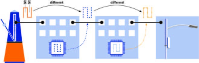
Between a clock source (such as a GPS receiver or an Atomic Clock) and the destination, there are several networking boxes (switches, routers, etc.). Each of those boxes clocksbits onto the fiber (or copper). Every time the clock ticks, another bit is sent. It doesn’t matter if it is a “1” bit or a “0” bit. It doesn’t matter if it is a real data bit or an idle bit. This clock is independent software and networking issues such as packet delay. It just depends on something, anything, to be continually transmitted. This clock could be the synchronization source, but only if it is the same as the clock source. And there’s the rub. Ethernet achieves its relatively low cost by transmitting data based on a clock chip local to each node, and the Ethernet standard allows this clock to be sloppy (± 100ppm). Connecting one box to an accurate source doesn’t solve the problem (see figure 1), each subsequent segment has a different clock.
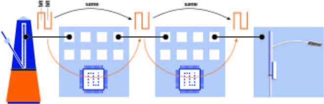
For cell site synchronization, the accurate bit clock must be replicated from node to node. Each node from the clock source to the cell site has to lock onto the incoming clock and then use it to transmit its data. This is called a synchronous network—all nodes are transmitting with the same clock—and in the case of Ethernet, it is called Synchronous Ethernetor SyncE (see figure 2). Note that SONET and SDH were designed this way so they are inherently synchronous.
Clearly, the Ethernet interfaces in each node are more complicated and more expensive. They need circuitry to lock on to the incoming bit clock and to clean up the clock, and then transfer the clock to the transmitter on other interfaces. None of these components can be “sloppy”; they all have to be high quality and accurate. And every node in the path has to support SyncE; if the chain is broken, synchronization is lost.
SyncE supports multiple clock sources for redundancy and provides a software-based method to choose the best one available. Each node periodically transmits a packet with an indication of how good its clock is, a Quality Level. The Quality Level can be based on the type of clock source, how many nodes has it gone through, etc. Each SyncE node chooses the clock from the incoming interface that is advertising the best quality. If that interface goes down, it chooses the next best, etc.
Synchronous Ethernet is an adaptation of a well-established and proven network synchronization model developed for SONET/SDH. The standards committee defined many of the parameters and tolerances to be identical to SONET/SDH which means that many of the same components can be used.
The primary downside of SyncE is that every node in the chain must support it. For green field installations this means just installing more expensive nodes. For existing networks, it requires a forklift upgrade which has its own economic impact. In this case using PTP for frequency synchronization (as well as time synchronization) might be an appropriate alternative.