How Can We Help?
Data Center Virtualization with VXLAN and EVPN
VXLAN using Unicast and Multicast Tunnels
- Non-EVPN: VXLANUnicast Traffic 8
- EVPN:VXLAN with EVPN Control Plane 11
- Non-EVPN:VXLAN with Data Plane Learning 16
- EVPN:VXLANTenant Identification using Port and VLAN 20
Glossary
VXLAN – Virtual extensible LAN
EVPN – Ethernet Virtual Private Network VM – Virtual Machine
PBB – Provider Backbone bridging OTV – Overlay Transport Virtualization
NVGRE – Network virtualization using Generic Route Encapsulation MPLS – Multiprotocol Label Switching
VPLS – Virtual Private LAN Service STT – Stateless Transport Tunelling
ISIS – Intermediate system – Intermediate system BGP – Border Gateway Protocol
MP-BGP – Multiprotocol Border Gateway Protocol
CHAPTER 1
Data Center Solution Overview
- DataCenter Virtualization
- VirtualizationTechnologies
- DataCenter Virtualization with VXLAN and EVPN
Data Center Virtualization
With the increase of data centers and huge amount of data that they store and manage and the increase in services, virtualization in data canters has been the need of the day. Server virtualization helps in reducing the cost to setup and manage a data center, as not only does it reduces the cost in buying and setting up the hardware, it also reduces the cost for cooling, electricity and maintenance. Also, most enterprise data centers are deployed in a hybrid cloud environment, which require the ability to expand, reduce or move their services/virtual machines.
Redeploying a service or a VM, needs support from the data center network. When new VMs have to be added in a data center or old VMs need to be moved, they should be added based on the compute availability and not because of the network configuration for the customer. This way the compute infrastructure is better utilized. In IP networks this requires reconfiguration of L3 infrastructure or a change in the customer VM IP address. This is not acceptable in a data center deployment. Tenants would want their VMs in the same subnet, wherever they are placed.
An overlay protocol can be used to connect the customer virtual machines (VMs) on servers located at different locations in the network to communicate without affecting the L3 infrastructure. The following sections discuss the technologies that can be used for this purpose.
Virtualization Technologies
An overlay is basically a tunneling protocol where the customer traffic can be tunneled across the network, without reconfiguring the network. Various tunneling technologies are in use in the enterprise and data center network.
- Q-in-Qtunneling or provider bridging provides a solution to scale beyond the 4K VLAN limitation, but it does not hide the customer MAC addresses from the core
PBB or Mac-in-Mac tunneling provided a solution to hide customer MAC addresses along with scaling, but it has a disadvantage on relying on xSTP protocols.
TRILL and SPB solved the issue of reliance on STP by using ISIS control plane learning. These technologies are deployable at the edge networks.
OTV and LISP are other tunneling technologies which address L2/L3 over L3 networks.
MPLS based VPLS and VPRN services provide VPN services within the data center and data center interconnect.
New host based virtualization technologies focus more on VM/Service mobility and multitenancy.
VXLAN, NVGRE and STT are some of the technologies developed in this area. VXLAN is the most popular among these as it is an UDP-based protocol allowing the network to use multiple paths. In this paper, VXLAN and EVPN will be discussed in details.
Data Center Virtualization with VXLAN and EVPN
VXLAN, NVGRE and STT are some of the technologies developed in this area. VXLAN is the most popular amongst these as it is an UDP based protocol providing the network to use multipaths. In this paper, VXLAN and EVPN will be discussed in details.
The VTEPs (Virtual Tunnel Endpoints) form UDP tunnels among themselves. VTEPs identify a specific tenant’s traffic and encapsulate it within the UDP tunnel. If the traffic is broadcast, multicast or unknown, then the traffic is multicasted over UDP to other VTEPs. A VXLAN header is inserted by the VTEP to identify the tenant of the traffic.
OcNOS supports VTEP functionality for VXLAN tunnels.
VXLAN depends on multicast and data plane learning to discover the VTEPs. To overcome this limitation, OcNOS supports EVPN control plane for VXLAN from Release 1.1 as beta quality.
EVPN is a control plane technology using MP-BGP for implementing VPN technologies in a network. EVPN was developed to provide the following improvements over the current VPN technologies.
- Controlplane learning
- Multicastoptimization
- Multihoming
- Simplicityin provisioning
- Achievingvarious services
- Betterreconvergence
When VXLAN is deployed in DCI, multicast and data plane learning are not preferred. A VXLAN solution with EVPN control plane is preferred in that deployment.
The next chapter describes the VXLAN and EVPN solution in OcNOS.
CHAPTER 2
VXLAN and EVPN Overview
- OcNOSVXLAN EVPN architecture
- VXLANusing unicast and multicast tunnels
- EVPNto learn VTEP topology
- Basic exampleconfigurations
OcNOS VXLAN EVPN Architecture
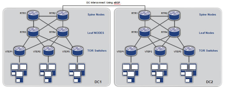
DC Interconnect Using eBGP
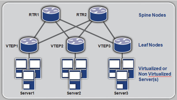
The above topology diagram demonstrates the network architecture which will be used to describe this solution. The access or top-of-rack (TOR) switches) implement the VTEP functionality. The Leaf node routers act as Route Reflectors and communicate within the data center. The Spine node routers act as second-level hierarchical Route Reflectors to communicate between different data centers using eBGP on the data center interconnect (DCI). MP-BGP is used at the routers and VTEPs to implement EVPN.
VXLAN using Unicast and Multicast Tunnels
VXLAN technology is defined in RFC 7348. The OcNOS implementation of VXLAN complies with the specification. In addition to providing the option of IP multicast for broadcast, unknown and multicast (BUM) traffic, the OcNOS implementation also provides an option for head-end replication of this kind of traffic.
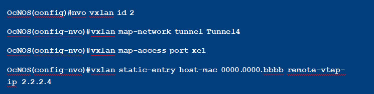
This configuration shows a unicast-only VXLAN VNID (Tenant), mostly used for ELINE services. Also shown in this configuration is mapping a port to a tenant and a static entry for a remote virtual machine MAC address.
This configuration shows a VXLAN VNID with IP multicast tunnels. All broadcast, unknown and multicast traffic will be sent on the tunnel destined to the multicast IP address specified in the configuration.

This configuration shows a VXLAN VNID with head-end replication. All broadcast, unknown and multicast traffic will be sent on all the unicast tunnels mapped to this tenant, in this case on both Tunnel4 and Tunnel5.
The tenant traffic can be identified through a port or through a port+VLAN identifier mapped to the tenant.
When a port is mapped to the tenant, all traffic arriving at the port is treated as the tenant traffic and
tunneled to remote VTEP(s) using the tenant id (VNID) in the VXLAN header.
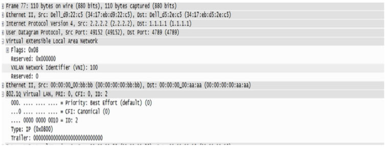
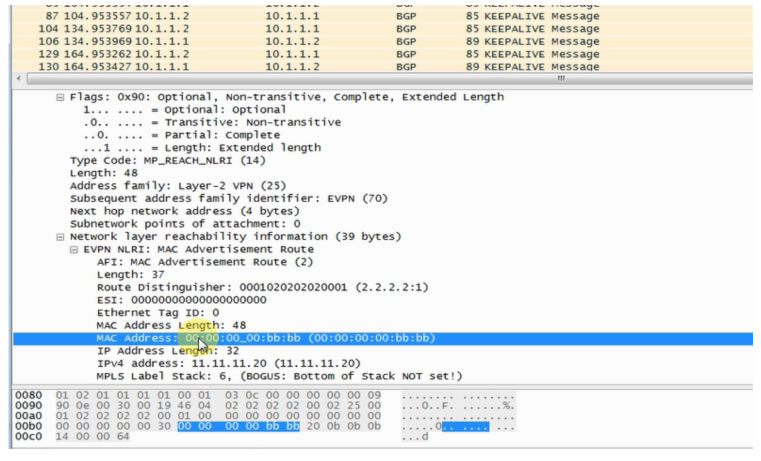
When a port+VLAN is mapped to the tenant, all traffic tagged with the specified VLAN arriving at the specified port is treated as the tenant traffic. When tunneled, the packet is encapsulated as shown in the below packet capture.
EVPN Learns VTEP Topology
EVPN was introduced in RFC 7432 for VPLS. EVPN was then extended for overlay technologies like VXLAN in draft-ietf-bess-evpn-overlay-02. The OcNOS EVPN solution complies with these standards. It is implemented only for the VXLAN data plane and is extensible to other data planes.
EVPN defines the use of MP-BGP protocol for learning the MAC/IP of the hosts connected to the VTEPs. The host MAC/IP is learned at the local VTEP through data plane learning. This is then transmitted to the other VTEPs through MP BGP. The remote VTEPs learn these routes at the tunnels connected to these VTEPs. The tunnels are learned automatically through MP-BGP.
In the configuration below, BGP neighbors are configured for the EVPN address family.

When configuring VXLAN VNIDs, it needs to be specified that EVPN will be used as a control plane. This is shown in the below configuration.
As can be seen in the above configuration, for VNIDs that will be using EVPN, there is no need to configure a tunnel, it will be automatically configured through BGP EVPN.
When a VNID is configured with EVPN, a BGP update message is sent to the EVPN neighbors with this information. This is the “Inclusive Multicast Ethernet Tag Route”. OcNOS supports only head end replication with EVPN. Once the tunnels are established on receiving this route, the MAC IP advertisements for host MAC and IP are distributed to the remote VTEPs using BGP-MP. This is
illustrated in the packet capture below. On receiving this route, the MAC/IP for the remote host is learned at this tunnel, and the packets will no longer be multicasted
At the route reflectors, the neighbors are configured as RR clients for the EVPN address family. The hierarchical RRs help load balance the intra and inter data center traffic.
Basic Example Configuration
1. Non-EVPN: VXLAN Unicast Traffic
This configuration has the following features:
- Dataplane learning
- ISIS configured as interior gatewayprotocol
- Theloopback interface is used as the VTEP IP
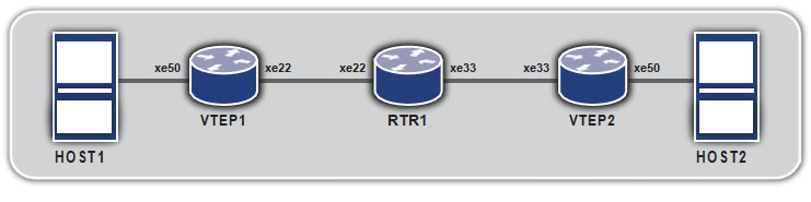
Topology
| C om man d | Purpose | |
| Step 1 | VTEP1#configure terminal | Entering configuration mode |
| Step 2 | VTEP1(con fi g)#bridge 1 protocol mstp | Creating bridge |
| Step 3 | VTEP1(con fi g)#interface xe50 | Configure xe50 interface. |
| Step 4 | VTEP1(con fi g-if)#switchport | Configure the port as L2 port. |
| Step 5 | V T E P 1 ( co n f i g – i f ) # b ri d g e – g ro u p 1 | Add the port to the bridge |
| Step 6 | VTEP1(con fi g-if)#switchport mode access | Set the port as access port |
| Step 7 | VTEP1(con fi g-if)#no shutdown | Set interface state as up |
| Step 8 | VTEP1(con fi g-if)#exit | Exit interface mode |
| Step 9 | VTEP1(con fi g)#interface xe22 | Configure xe22 interface |
| Step 10 | VTEP1(con fi g-if)#no switchport | Configure the port as L3 port. |
| Step 11 | VTEP1(con fi g-if)#ip address 11.11.11.1/24 | Configure IP address on the interface |
| Step 12 | VTEP1(con fi g-if)#no shutdown | Set interface state as up |
| Step 13 | VTEP1(con fi g-if)#exit | Exit interface mode |
| Step 14 | VTEP1(con fi g)#interface lo | Configure loopback interface |
| Step 15 | VTEP1(con fi g-if)#ip address 2.2.2.1/24 | Configure IP address on the interface |
| Step 16 | VTEP1(con fi g-if)#exit | Exit interface mode |
| Step 17 | VTEP1(con fi g)#router isis ipi | Configure ISIS as IGP. |
| Step 18 | VTEP1(con fi g-router)#is-type level-1 | Set the ISIS as Level 1. |
| Step 19 | VTEP1(con fi g-router)#net 49.0001.1111.1111.1111.00 | Establish a Network Entity Title for this instance, specifying the area address and the system ID. |
| Step 20 | VTEP1(con fi g-if)#exit | Exit router mode |
| Step 21 | VTEP1(con fi g)#interface lo | Configure loopback interface |
| Step 22 | VTEP1(con fi g-if)#ip router isis ipi | Enable IS-IS routing on an interface for area ipi |
| Step 23 | VTEP1(con fi g-if)#isis circuit-type level-1 | Set the circuit type for the interface lo |
| Step 24 | VTEP1(con fi g-if)#exit | Exit interface mode |
| Step 25 | VTEP1(con fi g)#interface xe22 | Configure xe22 interface |
| Step 26 | VTEP1(con fi g-if)#ip router isis ipi | Enable IS-IS routing on an interface for area ipi |
| Step 27 | VTEP1(con fi g-if)#isis circuit-type level-1 | Set the circuit type for the interface xe22 |
| Step 28 | VTEP1(con fi g-if)#exit | Exit interface mode |
| Step 29 | VTEP1(con fi g)#nvo vxlan enable | Enable VXLAN. Configure the node as VTEP. |
| Step 30 | VTEP1(con fi g)#interface tunnel 98 | Configure Tunnel interface |
| Step 31 | VTEP1(con fi g-if)#tunnel mode vxlan | Set the tunnel interface for vxlan |
| Step 32 | VTEP1(con fi g-if)#tunnel source 2.2.2.1 | Set the tunnel source ip |
| Step 33 | VTEP1(con fi g-if)#tunnel destination 3.3.3.1 | Set the tunnel destination ip |
| Step 34 | VTEP1(con fi g-if)#exit | Exit interface mode |
| Step 35 | VTEP1(con fi g)#nvo vxlan id 54321 ingress- replication | Configure a VXLAN VPN with head end replication |
| Step 36 | VTEP1(con fi g-nvo)#vxlan map-access port xe50 | Set xe50 as access port to VPN 54321 |
| Step 37 | V T E P 1 ( co n f i g – n v o ) # v x l a n m a p – n e t w ork t un n e l
Tunnel98 |
Set Tunnel98 as network tunnel for VPN 54321 |
| Step 38 | VTEP2(con fi g-nvo)#vxlan static-entry host-mac
0000.0000.bbbb remote-vtep-ip 3.3.3.1 |
Add a static entry for remote host |
| C om man d | Purpose | |
| Step 1 | VTEP2#configure terminal | Entering configuration mode |
| Step 2 | VTEP2(con fi g)#bridge 1 protocol mstp | Creating bridge |
| Step 3 | VTEP2(con fi g)#interface xe50 | Configure xe50 interface. |
| Step 4 | VTEP2(con fi g-if)#switchport | Configure the port as L2 port. |
| Step 5 | VTEP2(con fi g-if)#bridge-group 1 | Add the port to the bridge |
| Step 6 | VTEP2(con fi g-if)#switchport mode access | Set the port as access port |
| Step 7 | VTEP2(con fi g-if)#no shutdown | Set interface state as up |
| Step 8 | VTEP2(con fi g-if)#exit | Exit interface mode |
| Step 9 | VTEP2(con fi g)#interface xe33 | Configure xe33 interface |
| Step 10 | VTEP2(con fi g-if)#no switchport | Configure the port as L3 port. |
| Step 11 | VTEP2(con fi g-if)#ip address 12.12.12.1/24 | Configure IP address on the interface |
| Step 12 | VTEP2(con fi g-if)#no shutdown | Set interface state as up |
| Step 13 | VTEP2(con fi g-if)#exit | Exit interface mode |
| Step 14 | VTEP2(con fi g)#interface lo | Configure loopback interface |
| Step 15 | VTEP2(con fi g-if)#ip address 3.3.3.1/24 | Configure IP address on the interface |
| Step 16 | VTEP2(con fi g-if)#exit | Exit interface mode |
| Step 17 | VTEP2(con fi g)#router isis ipi | Configure ISIS as IGP. |
| Step 18 | VTEP2(con fi g-router)#is-type level-1 | Set the ISIS as Level 1. |
| Step 19 | VTEP2(con fi g-router)#net 49.0001.3333.3333.3333.00 | Establish a Network Entity Title for this instance, specifying the area address and the system ID. |
| Step 20 | VTEP2(con fi g-if)#exit | Exit router mode |
| Step 21 | VTEP2(con fi g)#interface lo | Configure loopback interface |
| Step 22 | VTEP2(con fi g-if)#ip router isis ipi | Enable IS-IS routing on an interface for area ipi |
| Step 23 | VTEP2(con fi g-if)#isis circuit-type level-1 | Set the circuit type for the interface lo |
| Step 24 | VTEP2(con fi g-if)#exit | Exit interface mode |
| Step 25 | VTEP2(con fi g)#interface xe33 | Configure xe33 interface |
| Step 26 | VTEP2(con fi g-if)#ip router isis ipi | Enable IS-IS routing on an interface for area ipi |
| Step 27 | VTEP2(con fi g-if)#isis circuit-type level-1 | Set the circuit type for the interface xe33 |
| Step 28 | VTEP2(con fi g-if)#exit | Exit interface mode |
| Step 29 | VTEP2(con fi g)#nvo vxlan enable | Enable VXLAN. Configure the node as VTEP. |
| Step 30 | VTEP2(con fi g)#interface tunnel 98 | Configure Tunnel interface |
| Step 31 | VTEP2(con fi g-if)#tunnel mode vxlan | Set the tunnel interface for vxlan |
| Step 32 | VTEP2(con fi g-if)#tunnel source 3.3.3.1 | Set the tunnel source ip |
| Step 33 | VTEP2(con fi g-if)#tunnel destination 2.2.2.1 | Set the tunnel destination ip |
| Step 34 | VTEP2(con fi g-if)#exit | Exit interface mode |
| Step 35 | VTEP2(con fi g)#nvo vxlan id 54321 ingress- replication | Configure a VXLAN VPN with head end replication |
| Step 36 | VTEP2(con fi g-nvo)#vxlan map-access port xe50 | Set xe50 as access port to VPN 54321 |
| Step 37 | VTEP2(con fi g-nvo)#vxlan map-network tunnel
Tunnel98 |
Set Tunnel98 as network tunnel for VPN 54321 |
| Step 38 | VTEP2(con fi g-nvo)#vxlan static-entry host-mac
0000.0000.aaaa remote-vtep-ip 2.2.2.1 |
Add a static entry for remote host |
| C om man d | Purpose | |
| Step 1 | RTR1#configure terminal | Entering configuration mode |
| Step 2 | RTR1(con fi g)#interface xe22 | Configure xe22 interface. |
| Step 3 | RTR1(con fi g-if)#no switchport | Configure the port as L3 port. |
| Step 4 | RTR1(con fi g-if)#ip address 11.11.11.2/24 | Configure IP address on the interface |
| Step 5 | RTR1(con fi g-if)#no shutdown | Set interface state as up |
| Step 6 | RTR1(con fi g-if)#exit | Exit interface mode |
| Step 7 | RTR1(con fi g)#interface xe33 | Configure xe33 interface |
| Step 8 | RTR1(con fi g-if)#no switchport | Configure the port as L3 port. |
| Step 9 | RTR1(con fi g-if)#ip address 12.12.12.2/24 | Configure IP address on the interface |
| Step 10 | RTR1(con fi g-if)#no shutdown | Set interface state as up |
| Step 11 | RTR1(con fi g-if)#exit | Exit interface mode |
| Step 12 | RTR1(con fi g)#router isis ipi | Configure ISIS as IGP. |
| Step 13 | RTR1(con fi g-router)#is-type level-1 | Set the ISIS as Level 1. |
| Step 14 | RTR1(con fi g-router)#net 49.0001.2222.2222.2222.00 | Establish a Network Entity Title for this instance, specifying the area address and the system ID. |
| Step 15 | RTR1(con fi g-if)#exit | Exit router mode |
| Step 16 | RTR1(con fi g)#interface xe22 | Configure xe22 interface |
| Step 17 | RTR1(con fi g-if)#ip router isis ipi | Enable IS-IS routing on an interface for area ipi |
| Step 18 | RTR1(con fi g-if)#isis circuit-type level-1 | Set the circuit type for the interface xe22 |
| Step 19 | RTR1(con fi g-if)#exit | Exit interface mode |
| Step 20 | RTR1(con fi g)#interface xe33 | Configure xe33 interface |
| Step 21 | RTR1(con fi g-if)#ip router isis ipi | Enable IS-IS routing on an interface for area ipi |
| Step 22 | RTR1(con fi g-if)#isis circuit-type level-1 | Set the circuit type for the interface xe33 |
| Step 23 | RTR1(con fi g-if)#exit | Exit interface mode |
2. EVPN: VXLAN with EVPN Control Plane
In this configuration, the transit BGP routers are Route Reflectors that are EBGP peers.
Topology
| C om man d | Purpose | |
| Step 1 | VTEP1#configure terminal | Entering configuration mode |
| Step 2 | VTEP1(con fi g)#bridge 1 protocol mstp | Creating bridge |
| Step 3 | VTEP1(con fi g)#interface xe50 | Configure xe50 interface. |
| Step 4 | VTEP1(con fi g-if)#switchport | Configure the port as L2 port. |
| Step 5 | V T E P 1 ( co n f i g – i f ) # b ri d g e – g ro u p 1 | Add the port to the bridge |
| Step 6 | VTEP1(con fi g-if)#switchport mode access | Set the port as access port |
| Step 7 | VTEP1(con fi g-if)#no shutdown | Set interface state as up |
| Step 8 | VTEP1(con fi g-if)#exit | Exit interface mode |
| Step 9 | VTEP1(con fi g)#interface xe27 | Configure xe27 interface |
| Step 10 | VTEP1(con fi g-if)#no switchport | Configure the port as L3 port. |
| Step 11 | VTEP1(con fi g-if)#ip address 3.3.3.1/24 | Configure IP address on the interface |
| Step 12 | VTEP1(con fi g-if)#no shutdown | Set interface state as up |
| Step 13 | VTEP1(con fi g-if)#exit | Exit interface mode |
| Step 14 | VTEP1(con fi g)#router isis ipi | Configure ISIS as IGP. |
| Step 15 | VTEP1(con fi g-router)#is-type level-2 only | Set the ISIS as Level 2 |
| Step 16 | VTEP1(con fi g-router)#net 49.0001.1111.1111.1111.00 | Establish a Network Entity Title for this instance, specifying the area address and the system ID. |
| Step 17 | VTEP1(con fi g-if)#exit | Exit router mode |
| Step 18 | VTEP1(con fi g)#interface xe27 | Configure xe27 interface |
| Step 19 | VTEP1(con fi g-if)#ip router isis ipi | Enable IS-IS routing on an interface for area ipi |
| Step 20 | VTEP1(con fi g-if)#isis circuit-type level-2 | Set the circuit type for the interface xe27 |
| Step 21 | VTEP1(con fi g-if)#exit | Exit interface mode |
| Step 22 | VTEP1(con fi g)#nvo vxlan enable | Enable VXLAN. Configure the node as VTEP. |
| Step 23 | VTEP1(con fi g)#nvo vxlan vtep-ip-global 3.3.3.1 | Configure the VTEP IP to be used in EVPN. |
| Step 24 | VTEP1(con fi g)#router bgp 1 | Configure BGP Router |
| Step 25 | V T E P 1 ( co n f i g – r o u t e r ) # n e i g h b o r 3 . 3 . 3 . 2 r e m o t e – a s 1 | Configure BGP neighbor |
| Step 26 | VTEP1(con fi -router)#address-family l2vpn evpn | Set the address family to evpn |
| Step 27 | V T E P 1 ( co n f i g – ro u t e r – a f ) # n e i g h b o r 3 . 3 . 3 . 2
activate |
Activate the neighbor for evpn address family. |
| Step 28 | VTEP1(con fi g-router-af)#exit | Exit address family mode |
| Step 29 | VTEP1(con fi g-router)#exit | Exit router mode |
| Step 30 | VTEP1(con fi g)#ip vrf vxlan100 | Configure VRF for EVPN |
| Step 31 | VTEP1(con fi g-vrf)#rd 100:1 | Configure Route Distinguisher |
| Step 32 | V T E P 1 ( co n f i g – v r f ) # r o u t e – t a r g e t b o t h 1 0 0 : 1 0 0 | Configure Route Target |
| Step 33 | VTEP1(con fi g-vrf)#exit | Exit VRF mode |
| Step 34 | VTEP1(con fi g)#nvo vxlan id 100 ingress- replication | Configure a VXLAN VPN with head end
replication |
| Step 35 | V T E P 1 ( co n f i g – n v o ) # v x l a n host-reachability-
protocol evpn-bgp vxlan100 |
Set EVPN based learning for VXLAN VPN 100 |
| Step 36 | VTEP1(con fi g-nvo)#vxlan map-access port xe50 | Set xe50 as access port to VPN 100 |
| Step 37 | VTEP1(con fi g-nvo)#exit | Exit NVO mode |
| C om man d | Purpose | |
| Step 1 | RTR1#configure terminal | Entering configuration mode |
| Step 2 | RTR1(con fi g)#interface xe27 | Configure xe27 interface |
| Step 3 | RTR1(con fi g-if)#no switchport | Configure the port as L3 port. |
| Step 4 | RTR1(con fi g-if)#ip address 3.3.3.2/24 | Configure IP address on the interface |
| Step 5 | RTR1(con fi g-if)#no shutdown | Set interface state as up |
| Step 6 | RTR1(con fi g-if)#exit | Exit interface mode |
| Step 7 | RTR1(con fi g)#interface xe25 | Configure xe25 interface |
| Step 8 | RTR1(con fi g-if)#no switchport | Configure the port as L3 port. |
| Step 9 | RTR1(con fi g-if)#ip address 2.2.2.2/24 | Configure IP address on the interface |
| Step 10 | RTR1(con fi g-if)#no shutdown | Set interface state as up |
| Step 11 | RTR1(con fi g-if)#exit | Exit interface mode |
| Step 12 | RTR1(con fi g)#router isis ipi | Configure ISIS as IGP. |
| Step 13 | RTR1(con fi g-router)#is-type level-2 only | Set the ISIS as Level 2 |
| Step 14 | RTR1(con fi g-router)#net 49.0001.2222.2222.2222.00 | Establish a Network Entity Title for this instance, specifying the area address and the system ID. |
| Step 15 | RTR1(con fi g-if)#exit | Exit router mode |
| Step 16 | RTR1(con fi g)#interface xe27 | Configure xe27 interface |
| Step 17 | RTR1(con fi g-if)#ip router isis ipi | Enable IS-IS routing on an interface for area ipi |
| Step 18 | RTR1(con fi g-if)#isis circuit-type level-2 | Set the circuit type for the interface xe27 |
| Step 19 | RTR1(con fi g-if)#exit | Exit interface mode |
| Step 20 | RTR1(con fi g)#interface xe25 | Configure xe25 interface |
| Step 21 | RTR1(con fi g-if)#ip router isis ipi | Enable IS-IS routing on an interface for area ipi |
| Step 22 | RTR1(con fi g-if)#isis circuit-type level-2 | Set the circuit type for the interface xe25 |
| Step 23 | RTR1(con fi g-if)#exit | Exit interface mode |
| Step 24 | RTR1(con fi g)#router bgp 1 | Configure BGP Router |
| Step 25 | R TR 1 ( co n f i g – r o u t e r ) # n e i g h b o r 2 . 2 . 2. 1 r e m o t e – a s 2 | Configure BGP neighbor |
| Step 26 | R TR 1 ( co n f i g – r o u t e r ) # n e i g h b o r 3 . 3 . 3 . 1 r e m o t e – a s 1 | Configure BGP neighbor |
| Step 27 | RTR1(con fi g-router)#address-family l2vpn evpn | Set the address family to evpn |
| Step 28 | RTR 1 ( co n f i g – r o u t e r – a f ) # n e i g h b o r 2.2.2.1
activate |
Activate the neighbor for evpn address family. |
| Step 29 | R TR 1 ( co n f i g – r o u t e r – a f ) # n e i g h b o r 3 . 3 . 3 . 1 a c t i v a te | Activate the neighbor for evpn address family. |
| Step 30 | R TR 1 ( co n f i g – ro u t e r – a f ) # n e i g h b o r 3 . 3 . 3 . 1
route-re fl ector-client |
Configure RR client for this RR |
| Step 31 | RTR1(con fi g-router-af)#exit | Exit address family mode |
| Step 32 | RTR1(con fi g-router)#exit | Exit router mode |
| C om man d | Purpose | |
| Step 1 | RTR2#configure terminal | Entering configuration mode |
| Step 2 | RTR2(con fi g)#interface xe25 | Configure xe25 interface |
| Step 3 | RTR2(con fi g-if)#no switchport | Configure the port as L3 port. |
| Step 4 | RTR2(con fi g-if)#ip address 2.2.2.1/24 | Configure IP address on the interface |
| Step 5 | RTR2(con fi g-if)#no shutdown | Set interface state as up |
| Step 6 | RTR2(con fi g-if)#exit | Exit interface mode |
| Step 7 | RTR2(con fi g)#interface xe11 | Configure xe11 interface |
| Step 8 | RTR2(con fi g-if)#no switchport | Configure the port as L3 port. |
| Step 9 | RTR2(con fi g-if)#ip address 4.4.4.1/24 | Configure IP address on the interface |
| Step 10 | RTR2(con fi g-if)#no shutdown | Set interface state as up |
| Step 11 | RTR2(con fi g-if)#exit | Exit interface mode |
| Step 12 | RTR2(con fi g)#router isis ipi | Configure ISIS as IGP. |
| Step 13 | RTR2(con fi g-router)#is-type level-2 only | Set the ISIS as Level 2 |
| Step 14 | RTR2(con fi g-router)#net 49.0001.3333.3333.3333.00 | Establish a Network Entity Title for this instance, specifying the area address and the system ID. |
| Step 15 | RTR2(con fi g-if)#exit | Exit router mode |
| Step 16 | RTR2(con fi g)#interface xe25 | Configure xe25 interface |
| Step 17 | RTR2(con fi g-if)#ip router isis ipi | Enable IS-IS routing on an interface for area ipi |
| Step 18 | RTR2(con fi g-if)#isis circuit-type level-2 | Set the circuit type for the interface xe25 |
| Step 19 | RTR2(con fi g-if)#exit | Exit interface mode |
| Step 20 | RTR2(con fi g)#interface xe11 | Configure xe11 interface |
| Step 21 | RTR2(con fi g-if)#ip router isis ipi | Enable IS-IS routing on an interface for area ipi |
| Step 22 | RTR2(con fi g-if)#isis circuit-type level-2 | Set the circuit type for the interface xe11 |
| Step 23 | RTR2(con fi g-if)#exit | Exit interface mode |
| Step 24 | RTR2(con fi g)#router bgp 2 | Configure BGP Router |
| Step 25 | RTR2(con fi g-router)#neighbor 2.2.2.2 remote-as 1 | Configure BGP neighbor |
| Step 26 | RTR2(con fi g-router)#neighbor 4.4.4.2 remote-as 2 | Configure BGP neighbor |
| Step 27 | RTR2(con fi g-router)#address-family l2vpn evpn | Set the address family to evpn |
| Step 28 | RTR2(con fi g-router-af)#neighbor 2.2.2.2 activate | Activate the neighbor for evpn address family. |
| Step 29 | RTR2(con fi g-router-af)#neighbor 4.4.4.2 activate | Activate the neighbor for evpn address family. |
| Step 30 | RTR2(con fi g-router-af)#neighbor 4.4.4.2
route-re fl ector-client |
Configure RR client for this RR |
| Step 31 | RTR2(con fi g-router-af)#exit | Exit address family mode |
| Step 32 | RTR2(con fi g-router)#exit | Exit router mode |
| C om man d | Purpose | |
| Step 1 | VTEP2#configure terminal | Entering configuration mode |
| Step 2 | VTEP2(con fi g)#bridge 1 protocol mstp | Creating bridge |
| Step 3 | VTEP2(con fi g)#interface xe50 | Configure xe50 interface. |
| Step 4 | VTEP2(con fi g-if)#switchport | Configure the port as L2 port. |
| Step 5 | VTEP2(con fi g-if)#bridge-group 1 | Add the port to the bridge |
| Step 6 | VTEP2(con fi g-if)#switchport mode access | Set the port as access port |
| Step 7 | VTEP2(con fi g-if)#no shutdown | Set interface state as up |
| Step 8 | VTEP2(con fi g-if)#exit | Exit interface mode |
| Step 9 | VTEP2(con fi g)#interface xe11 | Configure xe11 interface |
| Step 10 | VTEP2(con fi g-if)#no switchport | Configure the port as L3 port. |
| Step 11 | VTEP2(con fi g-if)#ip address 4.4.4.2/24 | Configure IP address on the interface |
| Step 12 | VTEP2(con fi g-if)#no shutdown | Set interface state as up |
| Step 13 | VTEP2(con fi g-if)#exit | Exit interface mode |
| Step 14 | VTEP2(con fi g)#router isis ipi | Configure ISIS as IGP. |
| Step 15 | VTEP2(con fi g-router)#is-type level-2 only | Set the ISIS as Level 2 |
| Step 16 | VTEP2(con fi g-router)#net 49.0001.4444.4444.4444.00 | Establish a Network Entity Title for this instance, specifying the area address and the system ID. |
| Step 17 | VTEP2(con fi g-if)#exit | Exit router mode |
| Step 18 | VTEP2(con fi g)#interface xe11 | Configure xe11 interface |
| Step 19 | VTEP2(con fi g-if)#ip router isis ipi | Enable IS-IS routing on an interface for area ipi |
| Step 20 | VTEP2(con fi g-if)#isis circuit-type level-2 | Set the circuit type for the interface xe27 |
| Step 21 | VTEP2(con fi g-if)#exit | Exit interface mode |
| Step 22 | VTEP2(con fi g)#nvo vxlan enable | Enable VXLAN. Configure the node as VTEP. |
| Step 23 | VTEP2(con fi g)#nvo vxlan vtep-ip-global 4.4.4.2 | Configure the VTEP IP to be used in EVPN. |
| Step 24 | VTEP2(con fi g)#router bgp 2 | Configure BGP Router |
| Step 25 | VTEP2(con fi g-router)#neighbor 4.4.4.1 remote-as 2 | Configure BGP neighbor |
| Step 26 | VTEP2(con fi g-router)#address-family l2vpn evpn | Set the address family to evpn |
| Step 27 | VTEP2(con fi g-router-af)#neighbor 4.4.4.1
activate |
Activate the neighbor for evpn address family. |
| Step 28 | VTEP2(con fi g-router-af)#exit | Exit address family mode |
| Step 29 | VTEP2(con fi g-router)#exit | Exit router mode |
| Step 30 | VTEP2(con fi g)#ip vrf vxlan100 | Configure VRF for EVPN |
| Step 31 | VTEP2(con fi g-vrf)#rd 101:1 | Configure Route Distinguisher |
| Step 32 | VTEP2(con fi g-vrf)#route-target both 100:100 | Configure Route Target |
| Step 33 | VTEP2(con fi g-vrf)#exit | Exit VRF mode |
| Step 34 | VTEP2(con fi g)#nvo vxlan id 100 ingress- replication | Configure a VXLAN VPN with head end
replication |
| Step 35 | VTEP2(config-nvo)#vxlan host-reachability-
protocol evpn-bgp vxlan100 |
Set EVPN based learning for VXLAN VPN 100 |
| Step 36 | VTEP2(con fi g-nvo)#vxlan map-access port xe50 | Set xe50 as access port to VPN 100 |
| Step 37 | VTEP2(con fi g-nvo)#exit | Exit NVO mode |
This configuration has the following features:
- TheVTEP is connected to more than one router
- Link failoverhappens when one router interface shuts down and then the packets are forwarded using the other router
Topology
VTEP1
| C om man d | Purpose | |
| Step 1 | VTEP1#configure terminal | Entering configuration mode |
| Step 2 | VTEP1(con fi g)#bridge 1 protocol mstp | Creating bridge |
| Step 3 | VTEP1(con fi g)#interface xe50 | Configure xe50 interface. |
| Step 4 | VTEP1(con fi g-if)#switchport | Configure the port as L2 port. |
| Step 5 | V T E P 1 ( co n f i g – i f ) # b ri d g e – g ro u p 1 | Add the port to the bridge |
| Step 6 | VTEP1(con fi g-if)#switchport mode access | Set the port as access port |
| Step 7 | VTEP1(con fi g-if)#no shutdown | Set interface state as up |
| Step 8 | VTEP1(con fi g-if)#exit | Exit interface mode |
| Step 9 | VTEP1(con fi g)#interface xe22 | Configure xe22 interface |
| Step 10 | VTEP1(con fi g-if)#no switchport | Configure the port as L3 port. |
| Step 11 | VTEP1(con fi g-if)#ip address 11.11.11.1/24 | Configure IP address on the interface |
| Step 12 | VTEP1(con fi g-if)#no shutdown | Set interface state as up |
| Step 13 | VTEP1(con fi g-if)#exit | Exit interface mode |
| Step 14 | VTEP1(con fi g)#interface xe25 | Configure xe25 interface |
| Step 15 | VTEP1(con fi g-if)#no switchport | Configure the port as L3 port. |
| Step 16 | VTEP1(con fi g-if)#ip address 21.21.21.1/24 | Configure IP address on the interface |
| Step 17 | VTEP1(con fi g-if)#no shutdown | Set interface state as up |
| Step 18 | VTEP1(con fi g-if)#exit | Exit interface mode |
| Step 19 | VTEP1(con fi g)#interface lo | Configure loopback interface |
| Step 20 | VTEP1(con fi g-if)#ip address 2.2.2.1/24 | Configure IP address on the interface |
| Step 21 | VTEP1(con fi g-if)#exit | Exit interface mode |
| Step 22 | VTEP1(con fi g)#router isis ipi | Configure ISIS as IGP. |
| Step 23 | VTEP1(con fi g-router)#is-type level-1 | Set the ISIS as Level 1. |
| Step 24 | VTEP1(con fi g-router)#net 49.0001.1111.1111.1111.00 | Establish a Network Entity Title for this instance, specifying the area address and the system ID. |
| Step 25 | VTEP1(con fi g-if)#exit | Exit router mode |
| Step 26 | VTEP1(con fi g)#interface lo | Configure loopback interface |
| Step 27 | VTEP1(con fi g-if)#ip router isis ipi | Enable IS-IS routing on an interface for area ipi |
| Step 28 | VTEP1(con fi g-if)#isis circuit-type level-1 | Set the circuit type for the interface lo |
| Step 29 | VTEP1(con fi g-if)#exit | Exit interface mode |
| Step 30 | VTEP1(con fi g)#interface xe22 | Configure xe22 interface |
| Step 32 | VTEP1(con fi g-if)#isis circuit-type level-1 | Set the circuit type for the interface xe22 |
| Step 33 | VTEP1(con fi g-if)#exit | Exit interface mode |
| Step 34 | VTEP1(con fi g)#interface xe22 | Configure xe22 interface |
| Step 35 | VTEP1(con fi g-if)#ip router isis ipi | Enable IS-IS routing on an interface for area ipi |
| Step 36 | VTEP1(con fi g-if)#isis circuit-type level-1 | Set the circuit type for the interface xe22 |
| Step 37 | VTEP1(con fi g-if)#exit | Exit interface mode |
| Step 38 | VTEP1(con fi g)#nvo vxlan enable | Enable VXLAN. Configure the node as VTEP. |
| Step 39 | VTEP1(con fi g)#interface tunnel 98 | Configure Tunnel interface |
| Step 40 | VTEP1(con fi g-if)#tunnel mode vxlan | Set the tunnel interface for vxlan |
| Step 41 | VTEP1(con fi g-if)#tunnel source 2.2.2.1 | Set the tunnel source ip |
| Step 42 | VTEP1(con fi g-if)#tunnel destination 3.3.3.1 | Set the tunnel destination ip |
| Step 43 | VTEP1(con fi g-if)#exit | Exit interface mode |
| Step 44 | VTEP1(con fi g)#nvo vxlan id 54321 ingress- replication | Configure a VXLAN VPN with head end
replication |
| Step 45 | VTEP1(con fi g-nvo)#vxlan map-access port xe50 | Set xe50 as access port to VPN 54321 |
| Step 46 | VTEP1(con fi g-nvo)#vxlan map-network tunnel
Tunnel98 |
Set Tunnel98 as network tunnel for VPN 54321 |
| Step 47 | VTEP1(con fi g-nvo)#vxlan static-entry host-mac
0000.0000.bbbb remote-vtep-ip 3.3.3.1 |
Add a static entry for remote host |
VTEP2
| C om man d | Purpose | |
| Step 1 | VTEP2#configure terminal | Entering configuration mode |
| Step 2 | VTEP2(con fi g)#bridge 1 protocol mstp | Creating bridge |
| Step 3 | VTEP2(con fi g)#interface xe50 | Configure xe50 interface. |
| Step 4 | VTEP2(con fi g-if)#switchport | Configure the port as L2 port. |
| Step 5 | VTEP2(con fi g-if)#bridge-group 1 | Add the port to the bridge |
| Step 6 | VTEP2(con fi g-if)#switchport mode access | Set the port as access port |
| Step 7 | VTEP2(con fi g-if)#no shutdown | Set interface state as up |
| Step 8 | VTEP2(con fi g-if)#exit | Exit interface mode |
| Step 9 | VTEP2(con fi g)#interface xe33 | Configure xe33 interface |
| Step 10 | VTEP2(con fi g-if)#no switchport | Configure the port as L3 port. |
| Step 11 | VTEP2(con fi g-if)#ip address 12.12.12.1/24 | Configure IP address on the interface |
| Step 12 | VTEP2(con fi g-if)#no shutdown | Set interface state as up |
| Step 13 | VTEP2(con fi g-if)#exit | Exit interface mode |
| Step 14 | VTEP2(con fi g)#interface lo | Configure loopback interface |
| Step 15 | VTEP2(con fi g-if)#ip address 3.3.3.1/24 | Configure IP address on the interface |
| Step 16 | VTEP2(con fi g-if)#exit | Exit interface mode |
| Step 17 | VTEP2(con fi g)#router isis ipi | Configure ISIS as IGP. |
| Step 18 | VTEP2(con fi g-router)#is-type level-1 | Set the ISIS as Level 1. |
| Step 19 | VTEP2(con fi g-router)#net 49.0001.3333.3333.3333.00 | Establish a Network Entity Title for this instance, specifying the area address and the system ID. |
| Step 20 | VTEP2(con fi g-if)#exit | Exit router mode |
| Step 21 | VTEP2(con fi g)#interface lo | Configure loopback interface |
| Step 22 | VTEP2(con fi g-if)#ip router isis ipi | Enable IS-IS routing on an interface for area ipi |
| Step 23 | VTEP2(config-if)#isis circuit-type level-1 | Set the circuit type for the interface lo |
| Step 24 | VTEP2(con fi g-if)#exit | Exit interface mode |
| Step 25 | VTEP2(con fi g)#interface xe33 | Configure xe33 interface |
| Step 26 | VTEP2(con fi g-if)#ip router isis ipi | Enable IS-IS routing on an interface for area ipi |
| Step 27 | VTEP2(con fi g-if)#isis circuit-type level-1 | Set the circuit type for the interface xe33 |
| Step 28 | VTEP2(con fi g-if)#exit | Exit interface mode |
| Step 29 | VTEP2(con fi g)#nvo vxlan enable | Enable VXLAN. Configure the node as VTEP. |
| Step 30 | VTEP2(con fi g)#interface tunnel 98 | Configure Tunnel interface |
| Step 31 | VTEP2(con fi g-if)#tunnel mode vxlan | Set the tunnel interface for vxlan |
| Step 32 | VTEP2(con fi g-if)#tunnel source 3.3.3.1 | Set the tunnel source ip |
| Step 33 | VTEP2(con fi g-if)#tunnel destination 2.2.2.1 | Set the tunnel destination ip |
| Step 34 | VTEP2(con fi g-if)#exit | Exit interface mode |
| Step 35 | VTEP2(con fi g)#nvo vxlan id 54321 ingress- replication | Configure a VXLAN VPN with head end
replication |
| Step 36 | VTEP2(con fi g-nvo)#vxlan map-access port xe50 | Set xe50 as access port to VPN 54321 |
| Step 37 | VTEP2(con fi g-nvo)#vxlan map-network tunnel
Tunnel98 |
Set Tunnel98 as network tunnel for VPN 54321 |
| Step 38 | VTEP2(con fi g-nvo)#vxlan static-entry host-mac
0000.0000.aaaa remote-vtep-ip 2.2.2.1 |
Add a static entry for remote host |
| C om man d | Purpose | |
| Step 1 | RTR1#configure terminal | Entering configuration mode |
| Step 2 | RTR1(con fi g)#interface xe22 | Configure xe22 interface. |
| Step 3 | RTR1(con fi g-if)#no switchport | Configure the port as L3 port. |
| Step 4 | RTR1(con fi g-if)#ip address 11.11.11.2/24 | Configure IP address on the interface |
| Step 5 | RTR1(con fi g-if)#no shutdown | Set interface state as up |
| Step 6 | RTR1(con fi g-if)#exit | Exit interface mode |
| Step 7 | RTR2(con fi g)#interface xe26 | Configure xe26 interface |
| Step 8 | RTR2(con fi g-if)#no switchport | Configure the port as L3 port. |
| Step 9 | RTR2(con fi g-if)#ip address 22.22.22.1/24 | Configure IP address on the interface |
| Step 10 | RTR2(con fi g-if)#no shutdown | Set interface state as up |
| Step 11 | RTR2(con fi g-if)#exit | Exit interface mode |
| Step 12 | RTR1(config)#interface xe33 | Configure xe33 interface |
| Step 13 | RTR1(con fi g-if)#no switchport | Configure the port as L3 port. |
| Step 14 | RTR1(con fi g-if)#ip address 12.12.12.2/24 | Configure IP address on the interface |
| Step 15 | RTR1(con fi g-if)#no shutdown | Set interface state as up |
| Step 16 | RTR1(con fi g-if)#exit | Exit interface mode |
| Step 17 | RTR1(con fi g)#router isis ipi | Configure ISIS as IGP. |
| Step 18 | RTR1(con fi g-router)#is-type level-1 | Set the ISIS as Level 1. |
| Step 19 | RTR1(con fi g-router)#net 49.0001.2222.2222.2222.00 | Establish a Network Entity Title for this instance, specifying the area address and the system ID. |
| Step 20 | RTR1(con fi g-if)#exit | Exit router mode |
| Step 21 | RTR1(con fi g)#interface xe22 | Configure xe22 interface |
| Step 22 | RTR1(con fi g-if)#ip router isis ipi | Enable IS-IS routing on an interface for area ipi |
| Step 23 | RTR1(con fi g-if)#isis circuit-type level-1 | Set the circuit type for the interface xe22 |
| Step 24 | RTR1(con fi g-if)#exit | Exit interface mode |
| Step 25 | RTR1(con fi g)#interface xe33 | Configure xe33 interface |
| Step 26 | RTR1(con fi g-if)#ip router isis ipi | Enable IS-IS routing on an interface for area ipi |
| Step 27 | RTR1(con fi g-if)#isis circuit-type level-1 | Set the circuit type for the interface xe33 |
| Step 28 | RTR1(con fi g-if)#exit | Exit interface mode |
| Step 29 | RTR2(con fi g)#interface xe26 | Configure xe26 interface |
| Step 30 | RTR2(con fi g-if)#ip router isis ipi | Enable IS-IS routing on an interface for area ipi |
| Step 31 | RTR2(con fi g-if)#isis circuit-type level-1 | Set the circuit type for the interface xe26 |
| Step 32 | RTR2(con fi g-if)#exit | Exit interface mode |
| C om man d | Purpose | |
| Step 1 | RTR2#configure terminal | Entering configuration mode |
| Step 2 | RTR2(con fi g)#interface xe25 | Configure xe25 interface. |
| Step 3 | RTR2(con fi g-if)#no switchport | Configure the port as L3 port. |
| Step 4 | RTR2(con fi g-if)#ip address 21.21.21.2/24 | Configure IP address on the interface |
| Step 5 | RTR2(con fi g-if)#no shutdown | Set interface state as up |
| Step 6 | RTR2(con fi g-if)#exit | Exit interface mode |
| Step 7 | RTR2(con fi g)#interface xe26 | Configure xe26 interface |
| Step 8 | RTR2(con fi g-if)#no switchport | Configure the port as L3 port. |
| Step 9 | RTR2(con fi g-if)#ip address 22.22.22.2/24 | Configure IP address on the interface |
| Step 10 | RTR2(con fi g-if)#no shutdown | Set interface state as up |
| Step 11 | RTR2(con fi g-if)#exit | Exit interface mode |
| Step 12 | RTR2(con fi g)#router isis ipi | Configure ISIS as IGP. |
| Step 13 | RTR2(con fi g-router)#is-type level-1 | Set the ISIS as Level 1. |
| Step 14 | RTR2(con fi g-router)#net 49.0001.4444.4444.4444.00 | Establish a Network Entity Title for this instance, specifying the area address and the system ID. |
| Step 15 | RTR2(con fi g-if)#exit | Exit router mode |
| Step 16 | RTR2(con fi g)#interface xe25 | Configure xe25 interface |
| Step 17 | RTR2(con fi g-if)#ip router isis ipi | Enable IS-IS routing on an interface for area ipi |
| Step 18 | RTR2(con fi g-if)#isis circuit-type level-1 | Set the circuit type for the interface xe25 |
| Step 19 | RTR2(con fi g-if)#exit | Exit interface mode |
| Step 20 | RTR2(con fi g)#interface xe26 | Configure xe26 interface |
| Step 21 | RTR2(con fi g-if)#ip router isis ipi | Enable IS-IS routing on an interface for area ipi |
| Step 22 | RTR2(con fi g-if)#isis circuit-type level-1 | Set the circuit type for the interface xe26 |
| Step 23 | RTR2(con fi g-if)#exit | Exit interface mode |
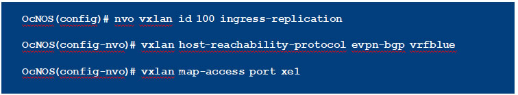
4. EVPN: VXLAN Tenant Identification using Port and VLAN
All the other test cases mentioned until have used only the port for identification. In this configuration, the VLAN identifier (2 in this example) is also used along with port to identify the tenant. So, data traffic must be tagged with the configured VLAN (2 in this case).
Topology
| C om man d | Purpose | |
| Step 1 | VTEP1#configure terminal | Entering configuration mode |
| Step 2 | VTEP1(con fi g)#bridge 1 protocol mstp | Creating bridge |
| Step 3 | VTEP1(con fi g)#vlan 2-10 bridge 1 state enable | Create VLANs for the bridge |
| Step 4 | VTEP1(con fi g)#interface xe50 | Configure xe50 interface. |
| Step 5 | VTEP1(con fi g-if)#switchport | Configure the port as L2 port. |
| Step 6 | V T E P 1 ( co n f i g – i f ) # b ri d g e – g ro u p 1 | Add the port to the bridge |
| Step 7 | VTEP1(con fi g-if)#switchport mode hybrid | Set the port as hybrid port |
| Step 8 | VTEP1(con fi g-if)#switchport hybrid allowed
vlan add 2 egress-tagged enable |
Make the port a member of VLAN 2 |
| Step 9 | VTEP1(con fi g-if)#no shutdown | Set interface state as up |
| Step 10 | VTEP1(con fi g-if)#exit | Exit interface mode |
| Step 11 | VTEP1(con fi g)#interface xe22 | Configure xe22 interface |
| Step 12 | VTEP1(con fi g-if)#no switchport | Configure the port as L3 port. |
| Step 13 | VTEP1(con fi g-if)#ip address 10.1.1.2/24 | Configure IP address on the interface |
| Step 14 | VTEP1(con fi g-if)#no shutdown | Set interface state as up |
| Step 15 | VTEP1(con fi g-if)#exit | Exit interface mode |
| Step 16 | VTEP1(con fi g)#interface lo | Configure lo interface |
| Step 17 | VTEP1(con fi g-if)#ip address 3.3.3.3/32 | Configure IP address on the interface |
| Step 18 | VTEP1(con fi g-if)#exit | Exit interface mode |
| Step 19 | VTEP1(con fi g)#router isis ipi | Configure ISIS as IGP. |
| Step 20 | VTEP1(con fi g-router)#is-type level-1 | Set the ISIS as Level 1 |
| Step 21 | VTEP1(con fi g-router)#net 49.0001.3333.3333.3333.00 | Establish a Network Entity Title for this instance, specifying the area address and the system ID. |
| Step 22 | VTEP1(con fi g-if)#exit | Exit router mode |
| Step 23 | VTEP1(con fi g)#interface xe22 | Configure xe22 interface |
| Step 24 | VTEP1(con fi g-if)#ip router isis ipi | Enable IS-IS routing on an interface for area ipi |
| Step 25 | VTEP1(con fi g-if)#isis circuit-type level-1 | Set the circuit type for the interface lo |
| Step 26 | VTEP1(con fi g-if)#exit | Exit interface mode |
| Step 27 | VTEP1(con fi g)#interface lo | Configure lo interface |
| Step 28 | VTEP1(con fi g-if)#ip router isis ipi | Enable IS-IS routing on an interface for area ipi |
| Step 29 | VTEP1(con fi g-if)#isis circuit-type level-1 | Set the circuit type for the interface lo |
| Step 30 | VTEP1(con fi g-if)#exit | Exit interface mode |
| Step 31 | VTEP1(con fi g)#nvo vxlan enable | Enable VXLAN. Configure the node as VTEP. |
| Step 32 | VTEP1(con fi g)#nvo vxlan vtep-ip-global 3.3.3.3 | Configure the VTEP IP to be used in EVPN. |
| Step 33 | VTEP1(con fi g)#router bgp 1 | Configure BGP Router |
| Step 34 | VTEP1(con fi g-router)#bgp router-id 3.3.3.3 | Configure BGP Router id |
| Step 35 | VTEP1(con fi g-router)#neighbor 10.1.1.1 remote-as 1 | Configure BGP neighbor |
| Step 36 | VTEP1(con fi -router)#address-family l2vpn evpn | Set the address family to evpn |
| Step 37 | V T E P 1 ( co n f i g – ro u t e r – a f ) # n e i g h b o r 1 0 .1.1.1
activate |
Activate the neighbor for evpn address family. |
| Step 38 | VTEP1(con fi g-router-af)#exit | Exit address family mode |
| Step 39 | VTEP1(con fi g-router)#exit | Exit router mode |
| Step 40 | VTEP1(con fi g)#ip vrf vxlan100 | Configure VRF for EVPN |
| Step 41 | VTEP1(con fi g-vrf)#rd 3.3.3.3:1 | Configure Route Distinguisher |
| Step 42 | V T E P 1 ( co n f i g – v r f ) # r o u t e – t a r g e t b o t h 3 . 3 . 3 . 3 : 1 | Configure Route Target |
| Step 43 | VTEP1(con fi g-vrf)#exit | Exit VRF mode |
| Step 44 | VTEP1(con fi g)#nvo vxlan id 100 ingress- replication | Configure a VXLAN VPN with head end
replication |
| Step 45 | VTEP1(con fi g-nvo)#vxlan host-reachability-
protocol evpn-bgp vxlan100 |
Set EVPN based learning for VXLAN VPN 100 |
| Step 46 | VTEP1(con fi g-nvo)#vxlan map-access port-vlan
xe50 2 |
Set xe50 and vlan 2 as access port to VPN 100 |
| Step 47 | VTEP1(con fi g-nvo)#exit | Exit NVO mode |
RTR1
| C om man d | Purpose | |
| Step 1 | RTR1#configure terminal | Entering configuration mode |
| Step 2 | RTR1(con fi g)#interface xe22 | Configure xe22 interface |
| Step 3 | RTR1(con fi g-if)#no switchport | Configure the port as L3 port. |
| Step 4 | RTR1(con fi g-if)#ip address 10.1.1.1/24 | Configure IP address on the interface |
| Step 5 | RTR1(con fi g-if)#no shutdown | Set interface state as up |
| Step 6 | RTR1(con fi g-if)#exit | Exit interface mode |
| Step 7 | RTR1(con fi g)#interface xe33 | Configure xe33 interface |
| Step 8 | RTR1(con fi g-if)#no switchport | Configure the port as L3 port. |
| Step 9 | RTR1(con fi g-if)#ip address 10.2.1.1/24 | Configure IP address on the interface |
| Step 10 | RTR1(con fi g-if)#no shutdown | Set interface state as up |
| Step 11 | RTR1(con fi g-if)#exit | Exit interface mode |
| Step 12 | RTR1(con fi g)#router isis ipi | Configure ISIS as IGP. |
| Step 13 | RTR1(con fi g-router)#is-type level 1 | Set the ISIS as Level 1 |
| Step 14 | RTR1(con fi g-router)#net 49.0001.2222.2222.2222.00 | Establish a Network Entity Title for this instance, specifying the area address and the system ID. |
| Step 15 | RTR1(con fi g-if)#exit | Exit router mode |
| Step 16 | RTR1(con fi g)#interface xe22 | Configure xe22 interface |
| Step 17 | RTR1(con fi g-if)#ip router isis ipi | Enable IS-IS routing on an interface for area ipi |
| Step 18 | RTR1(con fi g-if)#isis circuit-type level-1 | Set the circuit type for the interface xe22 |
| Step 19 | RTR1(con fi g-if)#exit | Exit interface mode |
| Step 20 | RTR1(con fi g)#interface xe33 | Configure xe33 interface |
| Step 21 | RTR1(con fi g-if)#ip router isis ipi | Enable IS-IS routing on an interface for area ipi |
| Step 22 | RTR1(con fi g-if)#isis circuit-type level-1 | Set the circuit type for the interface xe33 |
| Step 23 | RTR1(con fi g-if)#exit | Exit interface mode |
| Step 24 | RTR1(con fi g)#router bgp 1 | Configure BGP Router |
| Step 25 | RTR1(con fi g-router)#neighbor 10.1.1.2 remote-as 1 | Configure BGP neighbor |
| Step 26 | R TR 1 ( co n f i g – r o u t e r ) # n e i g h b o r 1 0 . 2.1 . 2 r e m o t e –
as 1 |
Configure BGP neighbor |
| Step 27 | R TR 1 ( co n f i g – r o u t e r ) # a d d re s s – f a m i l y l 2 v p n e v p n | Set the address family to evpn |
| Step 28 | R TR 1 ( co n f i g – r o u t e r – a f ) # n e i g h b o r 1 0 .1.1 . 2
activate |
Activate the neighbor for evpn address family. |
| Step 29 | R TR 1 ( co n f i g – ro u t e r – a f ) # n e i g h b o r 1 0 . 2.1 . 2
activate |
Activate the neighbor for evpn address family. |
| Step 30 | R TR 1 ( co n f i g – ro u t e r – a f ) # n e i g h b o r 1 0 .1.1 . 2
route-re fl ector-client |
Configure RR client for this RR |
| Step 31 | R TR 1 ( co n f i g – ro u t e r – a f ) # n e i g h b o r 1 0 . 2.1 . 2
route-re fl ector-client |
Configure RR client for this RR |
| Step 32 | RTR1(con fi g-router-af)#exit | Exit address family mode |
| Step 33 | RTR1(con fi g-router)#exit | Exit router mode |
VTEP2
| C om man d | Purpose | |
| Step 1 | VTEP2#configure terminal | Entering configuration mode |
| Step 2 | VTEP2(con fi g)#bridge 1 protocol mstp | Creating bridge |
| Step 3 | VTEP2(con fi g)#vlan 2-10 bridge 1 state enable | Create VLANs for the bridge |
| Step 4 | VTEP2(con fi g)#interface xe50 | Configure xe50 interface. |
| Step 5 | VTEP2(con fi g-if)#switchport | Configure the port as L2 port. |
| Step 6 | VTEP2(con fi g-if)#bridge-group 1 | Add the port to the bridge |
| Step 7 | VTEP2(con fi g-if)#switchport mode hybrid | Set the port as hybrid port |
| Step 8 | VTEP2(con fi g-if)#switchport hybrid allowed vlan
add 2 egress-tagged enable |
Make the port a member of VLAN 2 |
| Step 9 | VTEP2(con fi g-if)#no shutdown | Set interface state as up |
| Step 10 | VTEP2(con fi g-if)#exit | Exit interface mode |
| Step 11 | VTEP2(con fi g)#interface xe33 | Configure xe33 interface |
| Step 12 | VTEP2(con fi g-if)#no switchport | Configure the port as L3 port. |
| Step 13 | VTEP2(con fi g-if)#ip address 10.2.1.2/24 | Configure IP address on the interface |
| Step 14 | VTEP2(con fi g-if)#no shutdown | Set interface state as up |
| Step 15 | VTEP2(con fi g-if)#exit | Exit interface mode |
| Step 16 | VTEP2(con fi g)#interface lo | Configure lo interface |
| Step 17 | VTEP2(con fi g-if)#ip address 4.4.4.4/32 | Configure IP address on the interface |
| Step 18 | VTEP2(con fi g-if)#exit | Exit interface mode |
| Step 19 | VTEP2(con fi g)#router isis ipi | Configure ISIS as IGP. |
| Step 20 | VTEP2(con fi g-router)#is-type level-1 | Set the ISIS as Level 1 |
| Step 21 | VTEP2(con fi g-router)#net 49.0001.4444.4444.4444.00 | Establish a Network Entity Title for this instance, specifying the area address and the system ID. |
| Step 22 | VTEP2(con fi g-if)#exit | Exit router mode |
| Step 23 | VTEP2(con fi g)#interface xe33 | Configure xe33 interface |
| Step 24 | VTEP2(con fi g-if)#ip router isis ipi | Enable IS-IS routing on an interface for area ipi |
| Step 25 | VTEP2(con fi g-if)#isis circuit-type level-1 | Set the circuit type for the interface xe33 |
| Step 26 | VTEP2(con fi g-if)#exit | Exit interface mode |
| Step 27 | VTEP2(con fi g)#interface lo | Configure lo interface |
| Step 28 | VTEP2(con fi g-if)#ip router isis ipi | Enable IS-IS routing on an interface for area ipi |
| Step 29 | VTEP2(con fi g-if)#isis circuit-type level-1 | Set the circuit type for the interface lo |
| Step 30 | VTEP2(con fi g-if)#exit | Exit interface mode |
| Step 31 | VTEP2(con fi g)#nvo vxlan enable | Enable VXLAN. Configure the node as VTEP. |
| Step 32 | VTEP2(con fi g)#nvo vxlan vtep-ip-global 4.4.4.4 | Configure the VTEP IP to be used in EVPN. |
| Step 33 | VTEP2(con fi g)#router bgp 1 | Configure BGP Router |
| Step 34 | VTEP2(con fi g-router)#bgp router-id 4.4.4.4 | Configure BGP Router id |
| Step 35 | VTEP2(con fi g-router)#neighbor 10.2.1.1
remote-as 1 |
Configure BGP neighbor |
| Step 36 | VTEP2(con fi g-router)#address-family l2vpn evpn | Set the address family to evpn |
| Step 37 | VTEP2(con fi g-router-af)#neighbor 10.2.1.1
activate |
Activate the neighbor for evpn address family. |
| Step 38 | VTEP2(con fi g-router-af)#exit | Exit address family mode |
| Step 39 | VTEP2(con fi g-router)#exit | Exit router mode |
| Step 40 | VTEP2(con fi g)#ip vrf vxlan100 | Configure VRF for EVPN |
| Step 41 | VTEP2(con fi g-vrf)#rd 4.4.4.4:1 | Configure Route Distinguisher |
| Step 42 | VTEP2(con fi g-vrf)#route-target both 3.3.3.3:1 | Configure Route Target |
| Step 43 | VTEP2(con fi g-vrf)#exit | Exit VRF mode |
| Step 44 | VTEP2(con fi g)#nvo vxlan id 100 ingress- replication | Configure a VXLAN VPN with head end
replication |
| Step 45 | VTEP2(con fi g-nvo)#vxlan host-reachability-
protocol evpn-bgp vxlan100 |
Set EVPN based learning for VXLAN VPN 100 |
| Step 46 | VTEP2(con fi g-nvo)#vxlan map-access
port-vlan xe50 2 |
Set xe50 and vlan 2 as access port to VPN 100 |
| Step 47 | VTEP2(con fi g-nvo)#exit | Exit NVO mode |
Conclusion
OcNOS is a feature rich solution for data center deployments. VXLAN with EVPN is a perfect solution to provide various services especially in a multi-tenant and hybrid cloud environments. OcNOS is fully standards compliant in both these features.