Data Center Interconnect using MPLS
Chapter 1
Data Center Interconnect Overview
Data Center Interconnect Use Cases
Data Center Interconnect Technologies
Multipoint Interconnect using VPLS
Chapter 2
OcNOS DCI MPLS Overview
OcNOS DCI VPLS Architecture
Role determination using ICCP
VPLS Redundancy
MC-LAG in a Data Center using MPLS DCI
Basic Example Configuration
Conclusion
Glossary
| MPLS |
Multi protocol label switching |
| VPLS |
Virtual Pseudowire LAN services |
| VPWS |
VPWS – Virtual Pseudowire services |
| VxLAN |
Virtual Extensible LAN |
| OTV |
Overlay transport virtualization |
| LISP |
Locator/Identifier Separation Protocol |
| DCI |
Data center interconnect |
| MC-LAG |
Multi-Chassis LAG |
Chapter 1
Data Center Interconnect Overview
- Datacenter interconnect use-cases
- Datacenter interconnect technologies
- Multipoint interconnect using VPLS
Data Center Interconnect Use Cases
Data centers are usually not local to a particular geographical location. They span across regions and countries throughout the globe. Data centers often manage critical and voluminous data which poses a challenge to the networking technology.
The applications running inside the data center are agnostic to the interconnection technology and often treat data centers on different sites transparently. One requirement of having multiple data centers is to provide a High-
Availability clusters in which if one data center site fails, traffic can switch to the other without disruption. Another use case is server mobility across data center which is often done for load balancing or better user experience. A general requirement therefore is to have layer-2 connectivity between the data centers to expose a unified network towards the applications or the servers running in different data centers. MPLS data center interconnection is a viable choice as the sections below describe.
Data Center Interconnect Technologies
The popular ways of data center interconnects are;
- Dark Fiber
- IPBased
- MPLS Based
- Pointto Point interconnect using VPWS
- Multipointinterconnect using VPLS
Dark Fiber can give end to end layer 2 connectivity but is not always a feasible solution when sites are separated geographically over very wide areas. Using VxLAN for data center connectivity is an emerging technology. OcNOS has support for this but it will not be elaborated in this current document. OTV is a proprietary solution.
The preferred choice of data center interconnect (DCI) is using MPLS. This is a proven technology and most modern data centers are interconnected using MPLS. Sometimes large data center enterprises prefer owning the MPLS core nodes themselves, to have better flexibility in designing their data center interconnect solution. OcNOS enables them with this by its MPLS interconnect solution.
Layer 2VPN connectivity can be achieved by either VPWS or VPLS. VPWS can be only used when interconnecting two sites, while VPLS allows for a multi-site connectivity and therefore is more flexible. VPLS works by essentially creating multiple point to point MPLS tunnels carrying the Layer2 frame encapsulated. It uses a combination of LDP and/or BGP for peer discovery and signaling. This validated solution guide will explain how OcNOS switches can be used to connect multisite data centers using VPLS.
Multipoint Interconnect using VPLS
The following diagram shows a typical case of data center interconnect where three data center sites are involved. Generally it is preferred to have an IP/MPLS loop connection such that there is a backup path available in case of failure. In each data center two DCI core nodes are deployed as redundant to each other and there are two links between each data center site, each terminating on one of the redundant nodes.

DataCenter
SiteB
Data Center SiteA Data Center SiteC
There are two physical links between each data center
Note: Only the DCI core switches of each data center is shown.
Redundant Core Nodes (VPLS Enabled)
The data center core nodes terminate the Layer-2 network of the data center and map the traffic over VPLS to the other data center sites. Thus, the layer 2 domains of the each data center is extended onto the other.
Chapter 2
OcNOS DCI MPLS Overview
- OcNOSDCI MPLS architecture
- Roledetermination using ICCP
- VPLSredundancy
- MC-LAGin the data center using MPLS DCI
OcNOS DCI VPLS Architecture
Figure2. DCI VPLS Architecture

The above topology diagram demonstrates the network architecture on which this solution is developed.
The topology is a standard 3-tier architecture of access, aggregation and core nodes. OcNOS is running on all the nodes. The DCI core node is a layer 3 switch with MPLS enabled and is serving as the layer 2/layer 3 edge node. The aggregation and access nodes are layer 2 switches.
- The layer 3 switches (the DCI core nodes), terminate the layer 2 connections on one end and have VPLS deployed over the Data center The layer 3 switches run Inter-Chassis Communication protocol (ICCP). The same VPLS instance is running on both the DCI core nodes. ICCP synchronizes which node will act as the active/standby for a particular VPLS instance.
- Onthe layer 2 switches (the aggregation and access nodes), an IPI proprietary OcNOS Multi-Chassis Lag (MC-LAG) is deployed, which provides node redundancy as well as link MC-LAG is working in Active-Active mode.
The DCI Core nodes does load sharing based on VLANs which will be mapped to different VPLS instances. Some key features of this solution is
- Aggregation nodes are in MLAG Core Nodes are not in MLAG Domain.
- All the nodes have redundancy, and all are active in steady
- All the links have redundancy and working in active/active
Role determination using ICCP
ICCP protocol is defined in RFC 7275. The OcNOS implementation of ICCP is modelled on RFC 7275 with some proprietary implementations for better results. Two nodes form a ‘Redundancy Group’. An ICCP connection is established between the two nodes over a LDP connection.

ICCP exchanges the VPLS information between the redundant groups, and decides which VPLS instance will be Active/Standby. The administrator can give a preference primary/secondary for a certain VPLS instance on a node and based on that ICCP will choose on which node the VPLS instance will be made Active. The other will be standby. If no preference is given, admin preference is taken as primary, and then ICCP will do a tie-breaker and chooses one on its own logic.
As shown in the diagram below, VPLS-A had the admin role of primary but the operational role determined by ICCP by communicating with its redundant pair is secondary. So this VPLS instance will be standby and will not be forwarding any traffic mapped to it.

VPLS Redundancy
As mentioned earlier (See Figure DCI VPLS Architecture), the DCI core nodes terminate the layer 2 connections of the data center and extend it over to the other data center using VPLS. The core node which is running VPLS are connected to each other on different data centers. If the core node fails the entire data center connectivity will be lost.
Thus, it is very critical for the data center to have a redundancy on the core nodes. For the core node redundancy, VPLS redundancy is also required.
The following diagram shows how typically two data centers are interconnected. The PE nodes (DCI Core nodes) are dual homed to CEs nodes which are part of a MCLAG domain. MC-LAG expands the concept of link aggregation so that it provides node-level redundancy by allowing two or more nodes to share a common LAG endpoint. It emulates multiple nodes to represent as a single logical node to the remote node running Link aggregation. From the perspective of the PE nodes it can be considered that its ‘dual homed’ to a single CE node. The VPLS instances running in the
PE node, have attachment circuits as LAG ports (not MCLAG). Pseudo wires( which are essentially MPLS tunnels encapsulating the Layer2 circuits) are set up between each PE node in one data center to both the PE nodes in other data center. ICCP decides which VPLS instance will be made Active/Standby and based on that the pseudo wires corresponding to the VPLS instances exchange pseudo wire status messages. After negotiations, one pseudo wire per VPLS will be active between the data centers. In the figure, the standby Pseudo wires are shown in dotted lines and
the active in bold lines. For VPLS RED the pseudo wire between PE1 and PE4 is active. For VPLS Blue pseudo wire between PE2 and PE3 is active.
Figure3.VPLS Redundancy

VPLS redundancy always operates in Active/Standby mode, that is both nodes cannot be active simultaneously. Thus if there is a single VPLS instance only one core node in a data center will have an active VPLS and the other node will be standby and unutilized. That is why in solution design for data center adopted an approach to split the layer 2 traffic based on VLAN ranges and map them to two VPLS instances. Each node will have one active VPLS instance, and one standby VPLS instance. This is applicable if the VPLS attachment circuits are in Port+VLAN mode.

With reference to the topology in figure 3, the VLANs 2-200 are distributed between VPLS-Red and VPLS-Blue. In
data center 1, PE1 has VPLS-Red as ‘Active’, serving VLANs 2-100 and PE2 has VPLS-Blue as ‘Active’ serving VLANs 101-200. Thus the traffic is load balanced between the two redundant Nodes. The pseudo wires send status TLV corresponding to the active/standby status of the VPLS its part of and after negotiation one pseudo wire between the data centers will be up per VPLS.
Handling Failure Scenarios

In practice we can even have more than two VPLS instances dedicated to different ranges of VLANs, or even mapped to particular VLANs. If the preference given for a particular VPLS instance on both the redundant DCI core node is the same, ICCP will do a tie-breaker and select only one as active.
Note: The same VLAN should not be mapped to two different VPLS instances.
If the attachment circuit connected to a DCI core node is down, or the Node itself is down, the redundant node will take up all the operations.
The figure above(Figure: Handling Failure Scenarios) shows that PE1 is down. ICCP communication between the DCI core nodes detects this failure and thus PE2 will now host all the operations. Thus both the VPLS instances become active in PE2 node. The pseudo wire status is exchanged accordingly and again there will be one pseudo wire active per VPLS between the two data centers, in this case for VPLS Red between PE2 and PE4 and for VPLS Blue between PE2 and PE3.
MC-LAG in a Data Center using MPLS DCI
As explained earlier MC-LAG expands the concept of link aggregation so that it provides node-level redundancy by allowing two or more nodes to share a common LAG endpoint. It emulates multiple nodes to represent as a single logical node to the remote node running Link aggregation. As a result even if one of the nodes is down there exists a path to reach the destination via other nodes.
The topology in the figure “Handling Failure Scenarios” shows that DCI only deploys MC-LAG only at the Aggregation Nodes. The DCI Core nodes are not running it. However we still have link redundancy between Aggregation and DCI layer. This is because as shown in figure 4, there is a dual homing between each Aggregation node towards both the DCI core node. If the link CE1-PE1 fails, then CE2-PE1 link takes up by virtue of MC- LAG. If both the CE1-PE1, CE2-PE1 link fails, then ICCP will trigger switchover and the PE2 node will be active for all the VPLS instances.
Also there is no duplicate traffic going out of the DCI core nodes because they have VLAN-based load sharing, and a particular VLAN is taken up only by one of the two core nodes when both nodes are up. Thus, even though duplicate traffic reaches to the core nodes, it is dropped by the node which is not serving that particular VLAN. Guaranteeing a loop free topology.
Basic Example Configuration

PE1
| |
CLIcommand |
Purpose |
| Createtheinterfaces |
| Step 1 |
(config)#interface xe1 |
Enter interface mode. |
| Step 2 |
(config-if)#ip address 20.0.0.1/24 |
Configure ip address on ICCP interface |
| Step 3 |
(config-if)#label-switching |
Enable label switching |
| Step 4 |
(config-if)#exit |
Exit interface mode. |
| Step 5 |
(config)#interface xe46 |
Enter interface mode. |
| Step 5 |
(config-if)#ip address 11.0.0.1/24 |
Configure ip address on interface |
| Step 7 |
(config-if)#label-switching |
Enable label switching |
| Step 8 |
(config-if)#exit |
Exit interface mode. |
| Step 9 |
(config)#interface lo |
Enter interface mode. |
| Step 10 |
(config-if)#ip address 1.1.1.1/32 |
Set the IP address of the loopback interface |
| Step 11 |
(config-if)#exit |
Exit interface mode. |
| ConfigureOSPF |
| Step 12 |
(config)#router ospf |
Configure the OSPF routing process, |
| Step 13 |
(config-router)#network 1.1.1.1/32 area 0 |
Define the interfaces on which OSPF runs, and specify the backbone area 0. |
| Step 14 |
(config-router)#network 20.0.0.0/24 area 0 |
|
| Step 15 |
(config-router)#network 11.0.0.0/24 area 0 |
|
| Step 16 |
(config-router)#exit |
Exit Router mode. |
| ConfiguretheLDProuterinstanceandenableitontheinterface |
| Step 17 |
(config)#router ldp |
Enter Router LDP mode. |
| Step 18 |
(config-router)#pw-status-tlv |
|
| Step 19 |
(config-router)#transport-address ipv4 1.1.1.1 |
Configure the transport address for a label space by binding the address to a loopback address. |
| Step 20 |
(config-router)#targeted-peer ipv4 2.2.2.2 |
Specify the peers (PE2, PE3, and PE4) as targeted peers to enable targeted LDP session. |
| Step 21 |
(config-router)#targeted-peer ipv4 3.3.3.3 |
|
| Step 22 |
(config-router)#targeted-peer ipv4 4.4.4.4 |
|
| Step 23 |
(config-router)#keepalive-interval 1 |
|
| Step 24 |
(config-router)#keepalive-timeout 3 |
|
| Step 25 |
(config-router)#hello-interval 1 |
|
| Step 26 |
(config-router)#exit |
Exit Router mode. |
| Step 27 |
(config)#interface xe1 |
Enter interface mode. |
| Step 28 |
(config-if)#enable-ldp ipv4 |
Enable LDP on the specified interface. |
| Step 29 |
(config-if)#exit |
Exit interface mode. |
| Step 30 |
(config)#interface xe46 |
Enter interface mode. |
| Step 31 |
(config-if)#enable-ldp ipv4 |
Enable LDP on the specified interface. |
| Step 32 |
(config-if)#exit |
Exit interface mode. |
| ConfigureVPLSinstancesanddothebinding |
| Step 33 |
#configure terminal |
Enter Configure mode. |
| Step 34 |
(config)#mpls vpls VPLS-Red 1 |
Create an instance of VPLS, and switch to the VPLS command mode, by specifying the VPLS name (VPLS-Red) and VPLS ID (1). |
PE1 Cont.
| Step 35 |
(config-vpls)# redundancy-role primary |
Configure the redundancy Admin role of the VPLS instance. (By default the Redundancy admin role: Primary) |
| Step 36 |
(config-vpls)#vpls-type vlan |
Configure the VPLS as VLAN. |
| Step 37 |
(config-vpls)#signaling ldp |
Enter VPLS signaling LDP mode. |
| Step 38 |
(config-vpls-sig)#vpls-peer 3.3.3.3 |
Create a VPLS VC with peer core routers, PE3 and PE4 to which the mesh VC is to be associated by configuring the IP address of the peer nodes. |
| Step 39 |
(config-vpls-sig)#vpls-peer 4.4.4.4 |
|
| Step 40 |
(config-vpls-sig)#exit |
Exit signaling LDP mode. |
| Configure VPLS instances and do the binding |
| Step 41 |
(config)#mpls vpls VPLS-Blue 2 |
Create an instance of VPLS, and switch to the VPLS command mode, by specifying the VPLS name (VPLS-Blue) and VPLS ID (2). |
| Step 42 |
(config-vpls)#redundancy-role secondary |
Configure the redundancy Admin role of the VPLS instance. (By default the Redundancy admin role: Primary) |
| Step 43 |
(config-vpls)#vpls-type vlan |
Configure the VPLS as VLAN. |
| Step 44 |
(config-vpls)#signaling ldp |
Enter VPLS signaling LDP mode. |
| Step 45 |
(config-vpls-sig)#vpls-peer 3.3.3.3 |
Create a VPLS VC with peer core routers, PE3 and PE4 to which the mesh VC is to be associated by configuring the IP address of the peer nodes. |
| Step 46 |
(config-vpls-sig)#vpls-peer 4.4.4.4 |
|
| Step 47 |
(config-vpls-sig)#exit |
Exit signaling LDP mode. |
| Step 48 |
(config)#bridge 1 protocol rstp vlan-bridge |
Configure bridge |
| Step 49 |
(config) vlan 2-200 bridge 1 state enable |
Configure the VLANs |
| Step 50 |
(config)#int xe25 |
Enter interface mode |
| Step 51 |
(config-if)#switchport |
Switch to layer-2 mode |
| Step 52 |
(config-if)#bridge-group 1 |
Configure bridge group |
| Step 53 |
(config-if)#channel-group 2 mode active |
Add the interface to a layer 2 port channel |
| Step 54 |
(config)#int xe26 |
Enter interface mode |
| Step 55 |
(config-if)#switchport |
Switch to layer-2 mode |
| Step 56 |
(config-if)#bridge-group 1 |
Configure bridge group |
| Step 57 |
(config-if)#channel-group 2 mode active |
Add the interface to the same layer 2 port channel |
| Step 58 |
(config)#interface po2 |
Enter interface mode. ( Port channel ) |
| Step 59 |
(config-if)#switchport |
Switch to Layer-2 mode. (VPLS can be bound only on the Layer-2 port.) |
| Step 60 |
(config-if)#bridge-group 1 |
Configure bridge group |
| Step 61 |
(config-if)#switchport mode trunk |
For VLAN based vpls this config applies. |
| Step 62 |
(config-if)#switchport trunk allowed vlan add 2-200 |
Configure the VLANs that should be allowed this interface. |
| Step 63 |
config-if)#mpls-vpls VPLS-Red vlan 2-100 |
Associate an interface with the VPLS instance for VLAN binding by specifying the VPLS name on the interface and the VLAN ID. Repeat this step for all interfaces connected to CE devices associated with this VPLS instance. |
PE1 Cont.
| |
|
|
| Step 64 |
(config-if)#mpls-vpls VPLS-Blue vlan 101-200 |
Associate an interface with the VPLS instance for VLAN binding by specifying the VPLS name on the interface and the VLAN ID. Repeat this step for all interfaces connected to CE devices associated with this VPLS instance. |
| Step 65 |
(config)#redundancy interchassis group 1 |
Configure an ICCP group instance on router by specifying a valid group id. Note that the Group id should be same for both the ICCP peers. |
| Step 66 |
(config-red)#member ip 2.2.2.2 |
In redundancy mode, configure Member IP with the other ICCP peer. |
| Step 67 |
(config-red)#exit |
|
CE1
| |
CLIcommand |
Purpose |
| Step 1 |
(config)#bridge 1 protocol rstp vlan-bridge |
Configure Bridge |
| Step 2 |
(config)#interface xe47 |
Enter interface mode |
| Step 3 |
(config-if)#bridge-group 1 |
Associate bridge to interface |
| Step 4 |
(config-if)#switchport mode trunk |
Configure as Trunk port |
| Step 5 |
(config-if)#switchport trunk allowed vlan add 2-200 |
Configure the VLANs to allow through the port |
| Step 6 |
(config-if)#channel-group 1 mode active |
Associate the interface to portchannel -1 |
| Step 7 |
(config-if)#exit |
Exit interface mode. |
| Step 8 |
(config)#interface xe48 |
Enter interface mode. |
| Step 9 |
(config-if)#bridge-group 1 |
Associate the bridge to interface |
| Step 10 |
(config-if)#switchport mode trunk |
Configure interface as trunk |
| Step 11 |
(config-if)#switchport trunk allowed vlan add 2-200 |
Configure the VLANs to allow through the port |
| Step 12 |
(config-if)#channel-group 2 mode active |
Associate the interface to portchannel -1 |
| Step 13 |
(config-if)#exit |
Exit interface mode |
| Step 14 |
(config)#interface po1 |
Enter interface port channel mode |
| Step 15 |
(config-if)#mlag 1 |
Associate the port channel to mlag group -1 |
| Step 16 |
(config-if)#exit |
Exit interface mode |
| Step 17 |
(config)#interface po2 |
Enter interface port channel mode |
| Step 18 |
(config-if)#mlag 2 |
Associate the port channel to mlag group -2 |
| Step 19 |
(config-if)#exit |
Exit interface mode |
| Step 20 |
(config)#mcec domain configuration |
Enter Multichasis Etherchannel domain configuration mode. |
| Step 21 |
(config-mcec-domain)#domain-address 1111.2222.3333 |
Configure the domain address. |
| Step 22 |
(config-mcec-domain)#domain-system-number 1 |
Configure the domain system number. |
| Step 23 |
(config-mcec-domain)#intra-domain-link xe46 |
Specify the intra domain link for MLAG communication. |
| Step 24 |
(config-mcec-domain)#exit |
Exit MLAG mode |
CE2
| |
CLIcommand |
Purpose |
| Step 1 |
(config)#bridge 1 protocol rstp vlan-bridge |
Configure Bridge |
| Step 2 |
(config)#interface xe47 |
Enter interface mode |
| Step 3 |
(config-if)#bridge-group 1 |
Associate bridge to interface |
| Step 4 |
(config-if)#switchport mode trunk |
Configure as Trunk port |
CE2Cont.
| Step 5 |
(config-if)#switchport trunk allowed vlan add 2-200 |
Configure the VLANs to allow through the port |
| Step 6 |
(config-if)#channel-group 1 mode active |
Associate the interface to portchannel -1 |
| Step 7 |
(config-if)#exit |
Exit interface mode. |
| Step 8 |
(config)#interface xe48 |
Enter interface mode. |
| Step 9 |
(config-if)#bridge-group 1 |
Associate the bridge to interface |
| Step 10 |
(config-if)#switchport mode trunk |
Configure interface as trunk |
| Step 11 |
(config-if)#switchport trunk allowed vlan add 2-200 |
Configure the VLANs to allow through the port |
| Step 12 |
(config-if)#channel-group 2 mode active |
Associate the interface to portchannel -1 |
| Step 13 |
(config-if)#exit |
Exit interface mode |
| Step 14 |
(config)#interface po1 |
Enter interface port channel mode |
| Step 15 |
(config-if)#mlag 1 |
Associate the port channel to mlag group -1 |
| Step 16 |
(config-if)#exit |
Exit interface mode |
| Step 17 |
(config)#interface po2 |
Enter interface port channel mode |
| Step 18 |
(config-if)#mlag 2 |
Associate the port channel to mlag group -2 |
| Step 19 |
(config-if)#exit |
Exit interface mode |
| Step 20 |
(config)#mcec domain configuration |
Enter Multichasis Etherchannel domain configuration mode. |
| Step 21 |
(config-mcec-domain)#domain-address 1111.2222.3333 |
Configure the domain address. |
| Step 22 |
(config-mcec-domain)#domain-system-number 2 |
Configure the domain system number. |
| Step 23 |
(config-mcec-domain)#intra-domain-link xe46 |
Specify the intra domain link for MLAG communication |
| Step 24 |
(config-mcec-domain)#exit |
Exit MLAG mode |
PE3
| |
CLIcommand |
Purpose |
| Step 1 |
(config)# interface xe1 |
Enter interface mode. |
| Step 2 |
(config-if)# ip address 21.0.0.1/24 |
Configure ip address on ICCP interface |
| Step 3 |
(config-if)#label-switching |
|
| Step 4 |
(config-if)#exit |
Exit interface mode. |
| Step 5 |
(config)#interface xe46 |
Enter interface mode. |
| Step 6 |
(config-if)# ip address 11.0.0.2/24 |
Configure ip address on interface |
| Step 7 |
(config-if)#label-switching |
Enable label switching |
| Step 8 |
(config-if)#exit |
Exit interface mode. |
| Step 9 |
(config)#interface lo |
Enter interface mode. |
| Step 10 |
(config-if)# ip address 3.3.3.3/32 |
Set the IP address of the loopback interface |
| Step 11 |
(config-if)#exit |
Exit interface mode. |
| ConfigureOSPFontherouter |
| Step 12 |
(config)#router ospf |
Configure the OSPF routing process, |
| Step 13 |
(config-router)#network 3.3.3.3/32 area 0 |
Define the interfaces on which OSPF runs, and specify the backbone area 0. |
| Step 14 |
(config-router)#network 21.0.0.0/24 area 0 |
|
PE3Cont.
| Step 15 |
(config-router)#network 11.0.0.0/24 area 0 |
|
| Step 16 |
(config-router)#exit |
Exit Router mode. |
| Configure LDP router instance and enable on the interface |
| Step 17 |
(config)#router ldp |
Enter Router LDP mode. |
| Step 18 |
(config-router)#pw-status-tlv |
|
| Step 19 |
(config-router)# transport-address ipv4 3.3.3.3 |
Configure the transport address for a label space by binding the address to a loopback address. |
| Step 20 |
(config-router)#targeted-peer ipv4 1.1.1.1 |
Specify the peers ( PE2, PE3 and PE4) as targeted peers to enable targeted LDP session. |
| Step 21 |
(config-router)#targeted-peer ipv4 2.2.2.2 |
|
| Step 22 |
(config-router)#targeted-peer ipv4 4.4.4.4 |
|
| Step 23 |
(config-router)#keepalive-interval 1 |
|
| Step 24 |
(config-router)#keepalive-timeout 3 |
|
| Step 25 |
(config-router)#hello-interval 1 |
|
| Step 26 |
(config-router)#exit |
Exit Router mode. |
| Step 27 |
(config)#interface xe1 |
|
| Step 28 |
(config-if)#enable-ldp ipv4 |
|
| Step 29 |
(config-if)#exit |
|
| Step 30 |
(config)#interface xe46 |
Enter interface mode. |
| Step 31 |
(config-if)#enable-ldp ipv4 |
Enable LDP on the specified interface |
| Step 32 |
(config-if)#exit |
Exit interface mode. |
| Configure VPLS instances on the router and do the binding |
| Step 33 |
#configure terminal |
Enter Configure mode. |
| Step 34 |
(config)#mpls vpls VPLS-Red 1 |
Create an instance of VPLS, and switch to the VPLS command mode, by specifying the VPLS name (VPLS- Red) and VPLS ID (1). |
| Step 35 |
(config-vpls)# redundancy-role secondary |
Configure the redundancy Admin role of the VPLS instance. |
| Step 36 |
(config-vpls)#vpls-type vlan |
(By default the Redundancy admin role: Primary) |
| Step 37 |
(config-vpls)#signaling ldp |
Configure the VPLS as VLAN. |
| Step 38 |
(config-vpls-sig)#vpls-peer 1.1.1.1 |
Create a VPLS VC with peer core routers, PE3 and PE4 to which the mesh VC is to be associated by configuring the IP address of the peer nodes. |
| Step 39 |
(config-vpls-sig)#vpls-peer 2.2.2.2 |
|
| Step 40 |
(config-vpls-sig)#exit |
Exit signaling LDP mode. |
| Step 41 |
(config)#mpls vpls VPLS-Blue 2 |
Create an instance of VPLS, and switch to the VPLS command mode, by specifying the VPLS name (VPLS- Blue) and VPLS ID (2). |
| Step 42 |
(config-vpls)# redundancy-role primary |
Configure the redundancy Admin role of the VPLS instance. |
| Step 43 |
(config-vpls)#vpls-type vlan |
( By default the Redundancy admin role: Primary ) |
| Step 44 |
(config-vpls)#signaling ldp |
Configure the VPLS as VLAN. |
| Step 45 |
(config-vpls-sig)#vpls-peer 1.1.1.1 |
Create a VPLS VC with peer core routers, PE3 and PE4 to which the mesh VC is to be associated by configuring the IP address of the peer nodes. |
| Step 46 |
(config-vpls-sig)#vpls-peer 2.2.2.2 |
|
PE3Cont.
| Step 47 |
(config-vpls-sig)#exit |
Exit signaling LDP mode. |
| Step 48 |
(config)#bridge 1 protocol rstp vlan-bridge |
Configure bridge |
| Step 49 |
(config) vlan 2-200 bridge 1 state enable |
Configure the VLANs |
| Step 50 |
(config)#int xe25 |
Enter interface mode |
| Step 51 |
(config-if)#switchport |
Switch to layer-2 mode |
| Step 52 |
(config-if)#bridge-group 1 |
Configure bridge group |
| Step 53 |
(config-if)# channel-group 2 mode active |
Add the interface to a layer 2 port channel |
| Step 54 |
(config)#int xe26 |
Enter interface mode |
| Step 55 |
(config-if)#switchport |
Switch to layer-2 mode |
| Step 56 |
(config-if)#bridge-group 1 |
Configure bridge group |
| Step 57 |
(config-if)# channel-group 2 mode active |
Add the interface to the same layer 2 port channel |
| Step 58 |
(config)#interface po2 |
Enter interface mode. ( Port channel ) |
| Step 59 |
(config-if)#switchport |
Switch to Layer-2 mode. (VPLS can be bound only on the Layer-2 port.) |
| Step 60 |
(config-if)#bridge-group 1 |
|
| Step 61 |
(config-if)#switchport mode trunk |
Configure bridge group |
| Step 62 |
(config-if)#switchport trunk allowed vlan add 2-200 |
For VLAN based vpls this config applies. |
| Step 63 |
config-if)#mpls-vpls VPLS-Red vlan 2-100 |
Configure the VLANs that should be allowed on this interface |
| Step 64 |
(config-if)#mpls-vpls VPLS-Blue vlan 101-200 |
Associate an interface with the VPLS instance for VLAN binding by specifying the VPLS name on the interface and the VLAN ID. Repeat this step for all interfaces connected to CE devices associated with this VPLS instance. |
| Step 65 |
(config-if)#exit |
|
| Step 66 |
(config)# redundancy interchassis group 1 |
Associate an interface with the VPLS instance for VLAN binding by specifying the VPLS name on the interface and the VLAN ID. Repeat this step for all interfaces connected to CE devices associated with this VPLS instance. |
| Step 67 |
(config-red)#member ip 4.4.4.4 |
Configure an ICCP group instance on router by specifying a valid group id. (Pls note that the Group id should be same for both the ICCP peers) |
| Step 68 |
(config-red)#exit |
Under the Redundancy mode, configure Member IP with the other ICCP peer. |
PE4
| |
CLIcommand |
Purpose |
| Step 1 |
(config)# interface xe1 |
Enter interface mode. |
| Step 2 |
(config-if)#ip address 21.0.0.2/24 |
Configure ip address on ICCP interface |
| Step 3 |
(config-if)#label-switching |
|
| Step 4 |
(config-if)#exit |
Exit interface mode. |
| Step 5 |
(config)#interface xe46 |
Enter interface mode. |
| Step 6 |
(config-if)# ip address 30.0.0.2/24 |
Configure ip address on interface |
| Step 7 |
(config-if)#label-switching |
Enable label switching |
| Step 8 |
(config-if)#exit |
Exit interface mode. |
PE4Cont.
| Step 9 |
(config)#interface lo |
Enter interface mode. |
| Step 10 |
(config-if)# ip address 4.4.4.4/32 |
Set the IP address of the loopback interface |
| Step 11 |
(config-if)#exit |
Exit interface mode. |
| ConfigureOSPFontherouter |
| Step 12 |
(config)#router ospf |
Configure the OSPF routing process, |
| Step 13 |
(config-router)#network 4.4.4.4/32 area 0 |
Define the interfaces on which OSPF runs, and specify the backbone area 0. |
| Step 14 |
(config-router)#network 30.0.0.0/24 area 0 |
|
| Step 15 |
(config-router)#network 21.0.0.0/24 area 0 |
|
| Step 16 |
(config-router)#exit |
Exit Router mode. |
| Configure LDP router instance and enable on the interface |
| Step 17 |
(config)#router ldp |
Enter Router LDP mode. |
| Step 18 |
(config-router)# transport-address ipv4 4.4.4.4 |
Configure the transport address for a label space by binding the address to a loopback address. |
| Step 20 |
(config-router)#targeted-peer ipv4 1.1.1.1 |
Specify the peers ( PE1, PE3 and PE4) as targeted peers to enable targeted LDP session. |
| Step 21 |
(config-router)#targeted-peer ipv4 2.2.2.2 |
|
| Step 22 |
(config-router)#targeted-peer ipv4 3.3.3.3 |
|
| Step 23 |
(config-router)#keepalive-interval 1 |
|
| Step 24 |
(config-router)#keepalive-timeout 3 |
|
| Step 25 |
(config-router)#hello-interval 1 |
|
| Step 26 |
(config-router)#exit |
Exit Router mode. |
| Step 27 |
(config)#interface xe1 |
|
| Step 28 |
(config-router)#enable -ldp ipv4 |
|
| Step 29 |
(config-router)#exit |
|
| Step 30 |
(config)#interface xe46 |
Enter interface mode. |
| Step 31 |
(config-if)#enable-ldp ipv4 |
Enable LDP on the specified interface |
| Step 32 |
(config-if)#exit |
Exit interface mode. |
| Configure VPLS instances on the router and do the binding |
| Step 33 |
#configure terminal |
Enter Configure mode. |
| Step 34 |
(config)#mpls vpls VPLS-Red 1 |
Create an instance of VPLS, and switch to the VPLS command mode, by specifying the VPLS name (VPLS- Red) and VPLS ID (1). |
| Step 35 |
(config-vpls)# redundancy-role primary |
Configure the redundancy Admin role of the VPLS instance. |
| Step 36 |
(config-vpls)#vpls-type vlan |
Configure the VPLS as VLAN. |
| Step 37 |
(config-vpls)#signaling ldp |
Enter VPLS signaling LDP mode. |
| Step 38 |
(config-vpls-sig)#vpls-peer 1.1.1.1 |
Create a VPLS VC with peer core routers, PE3 and PE4 to which the mesh VC is to be associated by configuring the IP address of the peer nodes. |
| Step 39 |
(config-vpls-sig)#vpls-peer 2.2.2.2 |
|
| Step 40 |
(config-vpls-sig)#exit |
Exit signaling LDP mode. |
| Step 41 |
(config)#mpls vpls VPLS-Blue 2 |
Create an instance of VPLS, and switch to the VPLS command mode, by specifying the VPLS name (VPLS- Blue) and VPLS ID (2). |
PE4Cont.
| Step 42 |
(config-vpls)# redundancy-role secondary |
Configure the redundancy Admin role of the VPLS instance. |
| Step 43 |
(config-vpls)#vpls-type vlan |
( By default the Redundancy admin role: Primary ) |
| Step 44 |
(config-vpls)#signaling ldp |
Configure the VPLS as VLAN. |
| Step 45 |
(config-vpls-sig)#vpls-peer 1.1.1.1 |
Create a VPLS VC with peer core routers, PE3 and PE4 to which the mesh VC is to be associated by configuring the IP address of the peer nodes. |
| Step 46 |
(config-vpls-sig)#vpls-peer 2.2.2.2 |
|
| Step 47 |
(config-vpls-sig)#exit |
Exit signaling LDP mode. |
| Step 48 |
(config)#bridge 1 protocol rstp vlan-bridge |
Configure bridge |
| Step 49 |
(config) vlan 2-200 bridge 1 state enable |
Configure the VLANs |
| Step 50 |
(config)#interface xe25 |
Enter interface mode |
| Step 51 |
(config-if)#switchport |
Switch to layer-2 mode |
| Step 52 |
(config-if)#bridge-group 1 |
Configure bridge group |
| Step 53 |
(config-if)# channel-group 2 mode active |
Add the interface to a layer 2 port channel |
| Step 54 |
(config-if)#exit |
|
| Step 55 |
(config)#interface xe26 |
Enter interface mode |
| Step 56 |
(config-if)#switchport |
Switch to layer-2 mode |
| Step 57 |
(config-if)#bridge-group 1 |
Configure bridge group |
| Step 58 |
(config-if)#channel-group 2 mode active |
Add the interface to the same layer 2 port channel |
| Step 59 |
(config-if)#exit |
|
| Step 60 |
(config)#interface po2 |
Enter interface mode. ( Port channel ) |
| Step 61 |
(config-if)#switchport |
Switch to Layer-2 mode. (VPLS can be bound only on the Layer-2 port.) |
| Step 62 |
(config-if)#bridge-group 1 |
|
| Step 63 |
(config-if)#switchport mode trunk |
Configure bridge group |
| Step 64 |
(config-if)#switchport trunk allowed vlan add 2-200 |
For VLAN based vpls this config applies. |
| Step 65 |
config-if)#mpls-vpls VPLS-Red vlan 2-100 |
Configure the VLANs that should be allowed this interface |
| Step 66 |
(config-if)#mpls-vpls VPLS-Blue vlan 101-200 |
Associate an interface with the VPLS instance for VLAN binding by specifying the VPLS name on the interface and the VLAN ID. Repeat this step for all interfaces connected to CE devices associated with this VPLS instance. |
| Step 67 |
(config)# redundancy interchassis group 1 |
Associate an interface with the VPLS instance for VLAN binding by specifying the VPLS name on the interface and the VLAN ID. Repeat this step for all interfaces connected to CE devices associated with this VPLS instance. |
| Step 68 |
(config-red)#member ip 3.3.3.3 |
Configure an ICCP group instance on router by specifying a valid group id. ( Pls note that the Group id should be same for both the ICCP peers) |
| Step 69 |
(config-red)#exit |
Under the Redundancy mode, configure Member IP with the other ICCP peer. |
CE3
| |
CLIcommand |
Purpose |
| Step 1 |
(config)#bridge 1 protocol rstp vlan-bridge |
Configure Bridge |
| Step 2 |
(config)#interface xe47 |
Enter interface mode |
CE3Cont.
| Step 3 |
(config-if)# bridge-group 1 |
Associate bridge to interface |
| Step 4 |
(config-if)#switchport mode trunk |
Configure as Trunk port |
| Step 5 |
(config-if)#switchport trunk allowed vlan add 2-200 |
Configure the vlans to allow through the port |
| Step 6 |
(config-if)#channel-group 1 mode active |
Associate the interface to portchannel -1 |
| Step 7 |
(config-if)#exit |
Exit interface mode. |
| Step 8 |
(config)#interface xe48 |
Enter interface mode. |
| Step 9 |
(config-if)# bridge-group 1 |
Associate the bridge to interface |
| Step 10 |
(config-if)#switchport mode trunk |
Configure interface as trunk |
| Step 11 |
(config-if)#switchport trunk allowed vlan add 2-200 |
Configure the vlans to allow through the port. |
| Step 12 |
(config-if)#channel-group 2 mode active |
Associate the interface to portchannel -1 |
| Step 13 |
(config-if)#exit |
Exit interface mode |
| Step 14 |
(config)#interface po1 |
Enter interface port channel mode |
| Step 15 |
(config-if)#mlag 1 |
Associate the port channel to mlag group -1 |
| Step 16 |
(config-if)#exit |
Exit interface mode |
| Step 17 |
(config)#interface po2 |
Enter interface port channel mode |
| Step 18 |
(config-if)#mlag 2 |
Associate the port channel to mlag group -2 |
| Step 19 |
(config-if)#exit |
Exit interface mode |
| Step 20 |
(config)#mcec domain configuration |
Enter Multichasis Etherchannel domain configuration mode. |
| Step 21 |
(config-mcec-domain)#domain-address 1111.2222.3333 |
Configure the domain address. |
| Step 22 |
(config-mcec-domain)#domain-system-number 1 |
Configure the domain system number. |
| Step 23 |
(config-mcec-domain)#intra-domain-link xe46 |
Specify the intra domain link for MLAG communication |
| Step 24 |
(config-mcec-domain)#exit |
Exit MLAG mode |
CE4
| |
CLIcommand |
Purpose |
| Step 1 |
(config)#bridge 1 protocol rstp vlan-bridge |
Configure Bridge |
| Step 2 |
(config)#interface xe47 |
Enter interface mode |
| Step 3 |
(config-if)# bridge-group 1 |
Associate bridge to interface |
| Step 4 |
(config-if)#switchport mode trunk |
Configure as Trunk port |
| Step 5 |
(config-if)#switchport trunk allowed vlan add 2-200 |
Configure the vlans to allow through the port |
| Step 6 |
(config-if)#channel-group 1 mode active |
Associate the interface to portchannel -1 |
| Step 7 |
(config-if)#exit |
Exit interface mode. |
| Step 8 |
(config)#interface xe48 |
Enter interface mode. |
| Step 9 |
(config-if)# bridge-group 1 |
Associate the bridge to interface |
| Step 10 |
(config-if)#switchport mode trunk |
Configure interface as trunk |
| Step 11 |
(config-if)#switchport trunk allowed vlan add 2-200 |
Configure the vlans to allow through the port |
| Step 12 |
(config-if)#channel-group 2 mode active |
Associate the interface to portchannel -1 |
| Step 13 |
(config-if)#exit |
Exit interface mode |
| Step 14 |
(config)#interface po1 |
Enter interface port channel mode |
| Step 15 |
(config-if)#mlag 1 |
Associate the port channel to mlag group -1 |
| Step 16 |
(config-if)#exit |
Exit interface mode |
CE4Cont.
| Step 17 |
(config)#interface po2 |
Enter interface port channel mode |
| Step 18 |
(config-if)#mlag 2 |
Associate the port channel to mlag group -2 |
| Step 19 |
(config-if)#exit |
Exit interface mode |
| Step 20 |
(config)#mcec domain configuration |
Enter Multichasis Etherchannel domain configuration mode. |
| Step 21 |
(config-mcec-domain)#domain-address 1111.2222.3333 |
Configure the domain address. |
| Step 22 |
(config-mcec-domain)#domain-system-number 2 |
Configure the domain system number. |
PE2
| |
CLIcommand |
Purpose |
| Step 1 |
(config)# interface xe1 |
Enter interface mode. |
| Step 2 |
(config-if)#ip address 20.0.0.2/24 |
Configure address on ICCP interface. |
| Step 3 |
(config-if)#label-switching |
Enable label switching. |
| Step 4 |
(config-if)#exit |
Exit interface mode. |
| Step 5 |
(config)#interface xe46 |
Enter interface mode. |
| Step 6 |
(config-if)#ip address 30.0.0.1/24 |
Configure IP address on interface. |
| Step 7 |
(config-if)#label-switching |
Enable label switching. |
| Step 8 |
(config-if)#exit |
Exit interface mode. |
| Step 9 |
(config)#interface lo |
Enter interface mode. |
| Step 10 |
(config-if)#ip address 2.2.2.2/32 |
Set the IP address for the loopback interface. |
| Step 11 |
(config-if)#exit |
Exit interface mode. |
| ConfigureOSPFontherouter |
| Step 12 |
(config)#router ospf |
Configure the OSPF routing process. |
| Step 13 |
(config-router)#network 2.2.2.2/32 area 0 |
Define the interfaces on which OSPF runs and specify the backbone area 0. |
| Step 14 |
(config-router)#network 30.0.0.0/24 area 0 |
|
| Step 15 |
(config-router)#network 20.0.0.0/24 area 0 |
|
| Step 16 |
(config-router)#exit |
Exit router mode. |
| ConfigureLDProuterinstanceandenableitontheinterface |
| Step 17 |
(config)#router ldp |
Enter router LDP mode. |
| Step 18 |
(config-router)#pw-status-tlv |
|
| Step 19 |
(config-router)#transport-address ipv4 2.2.2.2 |
Configure the transport address for a label space by binding the address to the loopback address. |
| Step 20 |
(config-router)#targeted-peer ipv4 1.1.1.1 |
|
| Step 21 |
(config-router)#targeted-peer ipv4 3.3.3.3 |
|
| Step 22 |
(config-router)#targeted-peer ipv4 4.4.4.4 |
|
| Step 23 |
(config-router)#hello-interval 1 |
|
| Step 24 |
(config-router)#keepalive-timeout 3 |
|
| Step 25 |
(config-router)#hello-interval 1 |
|
| Step 26 |
(config-router)#exit |
Exit the router mode. |
| Step 27 |
(config)#interface xe1 |
Enter interface mode. |
| Step 28 |
(config-if)#enable-ldp ipv4 |
Enable LDP on the specified interface. |
| Step 29 |
(config-if)#exit |
Exit interface mode. |
| Step 30 |
(config)#interface xe46 |
Enter interface mode. |
| Step 31 |
(config-if)#enable-ldp ipv4 |
Enable LDP on the specified interface. |
| Step 32 |
(config-if)#exit |
|
PE2Cont.
| ConfigureVPLSinstancesontherouterandperrformthebinding |
| Step 33 |
#configure terminal |
Enter Configure mode. |
| Step 34 |
(config)#mpls vpls VPLS-Red 1 |
Create an instance of VPLS and switch to the VPLS command mode by specifying the VPLS name (VPLS- Red) and VPLS ID (1). |
| Step 35 |
config-vpls)#redundancy-role secondary |
Configure the redundancy ADMIN role of the VPLS instance. (By default, the redundancy admin role is primary). |
| Step 36 |
(config-vpls)#vpls-type vlan |
Configure the VPLS as VLAN. |
| Step 37 |
(config-vpls)#signaling ldp |
Enter VPLS signaling LDP mode. |
| Step 38 |
(config-vpls-sig)#vpls-peer 3.3.3.3 |
Create a VPLS VC with peer core routers, PE3 and PE4 to which the mesh VC is to be associated by configuring the IP address of the peer nodes. |
| Step 39 |
(config-vpls-sig)#vpls-peer 4.4.4.4 |
|
| Step 40 |
(config-vpls-sig)#exit |
Exit signaling LDP mode. |
| Step 41 |
(config)#mpls vpls VPLS-Blue 2 |
Create an instance of VPLS and switch to the VPLS commsnd mode by specifying the VPLS name (VPLS- Blue) and VPLS ID (2). |
| Step 42 |
(config-vpls)#redundancy-role primary |
Configure the redundancy Admin role of the VPLS instance. |
| Step 43 |
(config-vpls)#vpls-type vlan |
Configure the VPLS as VLAN. |
| Step 44 |
(config-vpls)#signaling ldp |
Enter VPLS signaling mode. |
| Step 45 |
(config-vpls-sig)#vpls-peer 3.3.3.3 |
Create a VPLS VC with peer core routers, PE3 and PE4 to which the mesh VC is to be associated by configuring the IP address of the peer nodes. |
| Step 46 |
(config-vpls-sig)#vpls-peer 4.4.4.4 |
|
| Step 47 |
(config-vpls-sig)#exit |
Exit signaling LDP mode. |
| Step 48 |
(config)#bridge 1 protocol rstp vlan-bridge |
Configure the bridge. |
| Step 49 |
(config)#vlan 2-200 bridge 1 state enable |
Configure the VLANs. |
| Step 50 |
(config)#interface xe25 |
Enter interface mode. |
| Step 51 |
(config-if)#switchport |
Switch to Layer-2 mode. |
| Step 52 |
(config-if)#bridge-group 1 |
Configure the bridge group. |
| Step 53 |
(config-if)#channel-group 2 mode active |
Add the interface to the Layer-2 port channel. |
| Step 54 |
(config-if)#exit |
Exit interfacce mode. |
| Step 55 |
(config)#interface xe26 |
Enter interface mode. |
| Step 56 |
(config-if)#switchport |
Switch to Layer-2 mode. |
| Step 57 |
(config-if)#bridge-group 1 |
Configure the bridge group. |
| Step 58 |
(config-if)#channel-group 2 mode active |
Add the interface to the same Layer-2 port channel. |
| Step 59 |
(config-if)#exit |
Exit interface mode. |
| Step 60 |
(config)#interface po2 |
Enter interface mode (Port Channel). |
| Step 61 |
(config-if)#switchport |
Switch to Layer-2 mode. The VPLS can be bound only on the Layer-2 port. |
| Step 62 |
(config-if)#bridge-group 1 |
Configure the bridge group. |
| Step 63 |
(config-if)#switchport mode trunk |
For VLAN-based VPLS, the configuration applies. |
| Step 64 |
(config-if)#switchport trunk allowed vlan add 2-200 |
Configure the VLANs that should be allowed on the interface. |
PE2Cont.
| Step 65 |
(config-if)#mpls-vpls VPLS-Red vlan 2-100 |
Associate an interface with the VPLS instance for VLAN binding by specifying the VPLS name on the interface and the VLAN ID. Repeat this step for all interfaces connected to CE devices associated with this VPLS instance. |
| Step 66 |
(config-if)#mpls-vpls VPLS-Blue vlan 101-200 |
Associate an interface with the VPLS instance for VLAN binding by specifying the VPLS name on the interface and the VLAN ID. Repeat this step for all interfaces connected to CE devices associated with this VPLS instance. |
| Step 67 |
(config-if)#exit |
Exit interface mode. |
| Step 68 |
(config)#redundancy interchassis group 1 |
Configure an ICCP group instance on router by specifying a valid group id. Note that the Group id should be same for both the ICCP peers. |
| Step 69 |
(config-red)#member ip 1.1.1.1 |
Under the Redundancy mode, configure member IP with the other ICCP peer. |
| Step 70 |
(config-red)#exit |
|
Conclusion
The OcNOS data center interconnect solution provides connectivity between the data centers enabling them to extend their Layer 2 network.
The OcNOS data center interconnect solution handles redundancy at all levels, including the core nodes using ICCP and VPLS redundancy. The links between aggregation and core are dual homed and redundant. In the aggregation and access nodes, the OcNOS MC-LAG solution provides both node and link level redundancy. Also, all the nodes and links are active and there are no unused links.
For more information:
EBGP-based Data Center with OcNOS
CHAPTER 1
Data Center Interconnect Overview
Large-Scale Data Center Requirements
Large-Scale Data Center Topologies
Large-Scale Data Center Routing
EBGP-Routed Clos Topology-Based Data Center
EBGP Data Center Design using OcNOS
CHAPTER 2
Configuration 8
ToR (leaf node)
Tier-2 (spine node)
Tier-3 (core node)
Tier-2 (border router)
Tier-3 (WAN router)
Other Configurations
Validation
Conclusion
References
Appendix A: Configuring the Data Center through NetConf
Appendix B: NetConf User Guide
Glossary
| BGP |
Border Gateway Routing Protocol |
| EBGP |
External BGP |
| STP |
Spanning Tree Protocol |
| TRILL |
Transparent Interconnection of Lots of Links |
| SPB |
Shortest Path Bridging |
| ECMP |
Equal Cost Multipath |
Chapter 1
Data Center Overview
Network Automation provides IT administrators and network operators significant benefits. This solution guide
describes an approach to build data centers using Layer3 BGP routing protocol.
It also summarizes on some design philosophies for data center and why E-BGP is better suited.
- Large-scaledata center requirements
- Large-scaledata center topologies
- Large-scaledata center routing
- EBGP-routedlarge-scale Clos topology-based data center
Large-Scale Data Center Requirements
The design of large-scale data centers is driven by operational simplicity and network stability. Operational simplicity and network stability ensures easier manageability and therefore reduced operational expenses. From the network design aspect, the requirements are:
- Abilityto accommodate the variable-application bandwidth and strict latency
- Abilityto handle the increased east-west (server-to-server) traffic within the data center due to massive
data replication between clusters and virtual machine migrations.
- Traffic-Engineeringwith application load The network infrastructure should itself perform controlled per-hop traffic engineering.
- MinimizeCAPEX and incorporate vendor diversity by using a simple, interoperable routing protocol with a minimal set of
- Adesign to minimize OPEX by keeping the failure domain at the lowest level in the network
Large-Scale Data Center Topologies
A traditional tree-based (upside down) topology with a three-layer hierarchy of core, aggregation and access
layer can be used in a data center design. This approach is suited if the majority of the traffic is entering
and leaving (north-south) the data center. An increase in bandwidth requirements then can be addressed by upgrading the device line cards or port density. However with the current trend of increasing server-to-server (east-west) traffic, scaling these networks horizontally is expensive or impossible at times.
A Clos network (leaf and spine) is a horizontally scalable topology where every leaf node is connected to every other spine. The topology can be extended to different stages for scaling. Clos networks are fully non- blocking and load balancing is inherent in the topology itself as all available paths are ECMP. Clos networks are ideal for the current requirements of a large-scale data center.
Large-Scale Data Center Routing
Layer 2-only routing was used in a traditional tree-based data center topology. Traditional layer-2 protocols such as STP do not give bi-sectional bandwidth, whereas recent developments such as TRILL, SPB have selected vendor support.
However, a hybrid of layer 2 /layer 3 can be used to limit the size of failure domain and scale up the data center. Layer 3 routing can be used in tier 1 (core) and layer 2 in tier 3 (access). Tier 2 can be based on either layer 2 or layer 3. A hybrid model has the advantage of seamless Virtual Machine mobility and requires less IP subnets for the data center. Although this design can scale-up, it is difficult and complex to manage the different protocols.
A layer 3 only design simplifies the network and improves network stability and scalability, as well as
localizing the failure domain (confined to the L2 broadcast domain). Seamless virtual mobility can be achieved in a L3 only based data center by using L2 overlay networks. From experiment and analysis, External BGP (EBGP) is considered ideal compared to IGPs due to the following [See Reference]:
- Lesscomplex protocol, simple state machine
- Informationflooding overhead is less, no frequent updates unlike IGPs
- Networkfailure recovery is very Although BGP convergence is slower than IGP, in a Clos topology with ECMP links, the failure is masked as soon as an alternate path is found.
- Failuredomain is minimized in a Clos topology with Some of the failures are local/hidden/not propagated if the failed link was not selected/advertised as the best path among the ECMP paths by the BGP speaker. The failures, where all devices have to withdraw some prefixes or update the ECMP groups in the FIB, are very limited and in those failures the failed link/node does not impact the re-convergence process.
- Administratorcan define the application traffic BGP provides services like prefix distribution, prefix filtering, traffic engineering, traffic tagging, and multi-vendor stability better than other IGPs.
- Easierto
EBGP-Routed CLOS Topology-Based Data Center
EBGP-routed CLOS topology is considered the best choice for laying the IP fabric in a data center because of the horizontal scalability feature of Clos topology and the ease of use and services provided by EBGP especially prefix-filtering, prefix distribution, and traffic engineering which are required extensively in a data center.
Configuration Guidelines
Configuration guidelines for laying IP fabric using EBGP efficiently are as follows:
- Runall EBGP sessions over single-hop point-to-point
- Useprivate Autonomous System Numbers (ASNs) (64512-65534) to avoid ASN
- Giveall tier 1 (core) devices a single
- Giveall tier 2 devices in the same cluster the same unique A cluster or pod is a group of tier 2 (spine switches) + tier 3 switches (ToR/leaf) + servers.
- Giveevery tier 3 (ToR) device in a cluster a unique
- Reusetier-3 ASNs across Configure tier-3 devices with the BGP “allowas-in” feature to allow route learning of prefixes from the same ASNs in other clusters.
- Announceserver subnets on tier-3 devices via BGP without using route summarization on tier-2 and tier-1
- Useedge clusters (pods) for external connectivity. Each edge cluster consists of border routers (tier-2) and WAN routers (tier-3). Give each WAN router a unique public ASN to connect the data center to the external world.
- Forborder routers, remove private ASNs before sending the information to WAN routers by configuring border routers with the “remove-private-AS” BGP
- Torelax the BGP ECMP criteria for AS paths, configure BGP “as-path multipath-relax” on all routers/ This way, an equal cost path with a different AS PATH, but the same AS PATH length is also considered an equal cost path (ECMP).
- Forfaster failure detection, configure the BGP session with
- Toavoid recurring BPG update/selection for a single failure through all peers or BGP update message dispersion on a particular speaker, use BGP update The BGP update group feature processes an update once and sends it to a group of neighbors that share a common outbound policy. The BGP RIB is scanned every time for each peer to apply the outbound filter.
- Toavoid micro routing loops, configure tier-2 and tier-1 with static discard or null routes rather than a default Routing loops can happen when a tier-2 device has lost all its learned prefixes, but has a default
route to a tier-1 device and that tier-1 device still has a route back to the tier-2 device.
EBGP Data Center Design using OcNOS
Figure-1 shows a minimal representation that encompasses all the elements in a layer 3 data center. The number of ECMPs in the data center is equal to the number of cores (tier-1 switches).
Figure 1 . IP fabric using EBGP
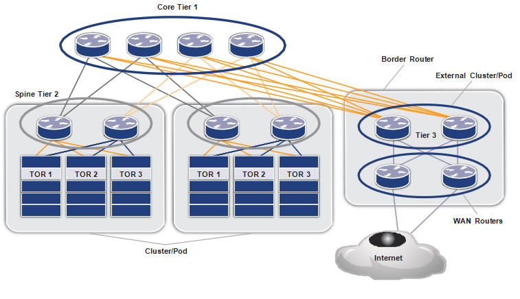 Core Tier 1
Figure 2 shows the Autonomous System Number (ASN) allocation scheme used in the data center. The WAN routers are assigned a public ASN, which connects the data center to external world. The tier-3 ASNs per ToR are reused across the clusters.
Figure 2: ASN allocation in an EBGP-based data center
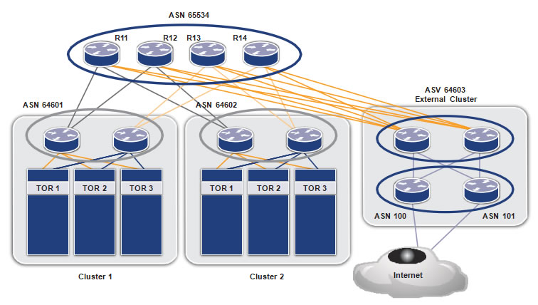 ASN 65534
Chapter 2
Configuration
To R (Leaf node)
| |
Command |
Purpose |
| Step 1 |
(config)#interface xe1 |
Enter interface mode. |
| Step 2 |
(config-if)#ip address 32.1.0.3/24 |
Configure ip address on the Interface |
| Step 3 |
(config-if)#exit |
Exit interface mode. |
| Step 4 |
(config)#interface xe2 |
Enter interface mode. |
| Step 5 |
(config-if)#exit |
Exit interface mode. |
| Step 6 |
(config)#router bgp 65500 |
Configure the EBGP routing process with private ASN |
| Step 7 |
(config-router)#max-paths ebgp 8 |
Exit interface mode. |
| Step 8 |
(config-router)#neighbor 32.1.0.2 remote-as 64601 |
Configure maximum EBGP ECMP that can be installed in BGP. |
| Step 9 |
(config-router)#neighbor 32.1.0.2 fall-over bfd |
Configure the EBGP neighbor over the connected interface using the neighbor IP and remote private ASN |
| Step 10 |
(config-router)#neighbor 32.1.0.2 allowas-in |
Configure BFD for the BGP session for faster failure detection. |
| Step 11 |
(config-router)#neighbor 32.2.0.2 remote-as 64601 |
Configure “allowas-in” for the neighbor to accept routes with same ASN learned over this neighbor |
| Step 12 |
(config-router)#neighbor 32.2.0.2 fall-over bfd |
Configure the EBGP neighbor over the connected interface using the neighbor IP and remote private ASN |
| Step 13 |
(config-router)#neighbor 32.2.0.2 allowas-in |
Configure BFD for the BGP session for faster failure detection. |
| Step 14 |
(config-router)#exit |
Configure “allowas-in” for the neighbor to accept routes with same ASN learned over this neighbor |
| Step 15 |
(config-router)#exit |
Exit Router mode. |
Tier-2 (Spine node)
| |
Command |
Purpose |
| Configure the interfaces |
| Step 1 |
(config)#interface xe1 |
Enter interface mode. |
| Step 2 |
(config-if)#ip address 32.1.0.2/24 |
Configure ip address on the interface |
| Step 3 |
(config-if)#exit |
Exit interface mode. |
| Step 4 |
(config)#interface xe46 |
Enter interface mode. |
| Step 5 |
(config-if)#ip address 32.3.0.2/24 |
Configure an IP address on the interface |
| Step 6 |
(config)#interface xe47 |
Enter interface mode. |
| Step 7 |
(config-if)#ip address 32.4.0.2/24 |
Configure an IP address on the interface |
| Step 8 |
(config)#interface xe48 |
Enter interface mode. |
| Step 9 |
(config-if)#ip address 21.1.0.2/24 |
Configure an IP address on the interface |
| Step 10 |
(config)#interface xe46 |
Enter interface mode. |
| Step 11 |
(config-if)#ip address 21.2.0.2/24 |
Configure an IP address on the interface |
| Step 12 |
(config)#router bgp 64601 |
Configure the eBGP routing process with private ASN |
| |
Command |
Purpose |
| Configure BGP on the router |
| Step 13 |
(config-router)#bgp bestpath as-path multipath-relax |
Configure “as-path multipath-relax” to relax the AS-PATH exact match (if AS-PATH length are same) criteria for BGP ECMP |
| Step 14 |
(config-router)#max-paths ebgp 8 |
Configure maximum EBGP ECMP that can be installed in BGP. |
| Step 15 |
(config-router)#neighbor 32.1.0.3 remote-as 65000 |
Configure the EBGP neighbor over the connected interface using the neighbor IP and remote ASN |
| Step 16 |
(config-router)#neighbor 32.1.0.3 fall-over bfd |
Configure BFD for the BGP session for faster failure detection. |
| Step 17 |
(config-router)#neighbor 32.3.0.3 remote-as 65001 |
Configure the EBGP neighbor over the connected interface using the neighbor IP and remote ASN |
| Step 18 |
(config-router)#neighbor 32.3.0.3 fall-over bfd |
Configure BFD for the BGP session for faster failure detection. |
| Step 19 |
(config-router)#neighbor 32.4.0.3 remote-as 65002 |
Configure the EBGP neighbor over the connected
interface using the neighbor IP and remote ASN |
| Step 20 |
(config-router)#neighbor 32.1.0.3 fall-over bfd |
Configure BFD for the BGP session for faster failure
detection. |
| Step 21 |
(config-router)#neighbor 21.1.0.1 remote-as 65534 |
Configure the EBGP neighbor over the connected interface using the neighbor IP and remote ASN |
| Step 22 |
(config-router)#neighbor 21.1.0.1 fall-over bfd |
Configure BFD for the BGP session for faster failure detection. |
| Step 23 |
(config-router)#neighbor 21.2.0.1
remote-as 65534 |
Configure the EBGP neighbor over the connected interface using the neighbor IP and remote ASN |
| Step 24 |
(config-router)#neighbor 21.2.0.1 fall-over bfd |
Configure BFD for the BGP session for faster failure detection. |
| Step 25 |
(config-router)#exit |
Exit Router mode. |
Tier-3 (Core node)
| |
Command |
Purpose |
| Configure the interfaces |
| Step 1 |
(config)#interface xe1 |
Enter interface mode. |
| Step 2 |
(config-if)#ip address 21.1.0.1/24 |
Configure ip address on the interface |
| Step 3 |
(config-if)#exit |
Exit interface mode. |
| Step 4 |
(config)#interface xe46 |
Enter interface mode. |
| Step 5 |
(config-if)#ip address 21.5.0.1/24 |
Configure an IP address on the interface |
| Step 6 |
(config)#interface xe49 |
Enter interface mode. |
| Step 7 |
(config-if)#ip address 41.1.0.1/24 |
Configure an IP address on the interface |
| Step 8 |
(config)#interface xe50 |
Enter interface mode. |
| Step 9 |
(config-if)#ip address 41.5.0.1/24 |
Configure an IP address on the interface |
| Configure BGP on the router |
| Step 10 |
(config)#router bgp 65534 |
Configure the eBGP routing process with private ASN |
| Step 11 |
(config-router)#bgp bestpath as-path multipath-relax |
Configure “as-path multipath-relax” to relax the AS-PATH exact match (if AS-PATH length are same) criteria for BGP ECMP |
| Step 12 |
(config-router)#max-paths ebgp 8 |
Configure maximum EBGP ECMP that can be installed
in BGP. |
| Step 13 |
(config-router)#neighbor 21.1.0.2
remote-as 64601 |
Configure the EBGP neighbor over the connected
interface using the neighbor IP and remote ASN |
| Step 14 |
(config-router)#neighbor 21.1.0.2 fall-over bfd |
Configure BFD for the BGP session for faster failure
detection. |
| Step 15 |
(config-router)#neighbor 21.5.0.3
remote-as 64602 |
Configure the EBGP neighbor over the connected
interface using the neighbor IP and remote ASN |
| Step 16 |
(config-router)#neighbor 21.5.0.3 fall-over bfd |
Configure BFD for the BGP session for faster failure
detection. |
| Step 17 |
(config-router)#neighbor 41.1.0.3
remote-as 64603 |
Configure the EBGP neighbor over the connected
interface using the neighbor IP and remote ASN |
| Step 18 |
(config-router)#neighbor 41.1.0.3 fall-over bfd |
Configure BFD for the BGP session for faster failure
detection. |
| Step 19 |
(config-router)#neighbor 41.5.0.3
remote-as 64603 |
Configure the EBGP neighbor over the connected
interface using the neighbor IP and remote ASN |
| Step 20 |
(config-router)#neighbor 41.5.0.3 fall-over bfd |
Configure BFD for the BGP session for faster failure
detection. |
| Step 21 |
(config-router)#exit |
Exit BGP mode |
Tier 2 (Border router)
| |
Command |
Purpose |
| Configure the interfaces |
| Step 1 |
(config)#interface xe1 |
Enter interface mode. |
| Step 2 |
(config-if)#ip address 41.1.0.2/24 |
Configure an IP address on the interface |
| Step 3 |
(config-if)#exit |
Exit interface mode. |
| Step 4 |
(config)#interface xe46 |
Enter interface mode. |
| Step 5 |
(config-if)#ip address 41.2.0.2/24 |
Configure an IP address on the interface |
| Step 6 |
(config)#interface xe47 |
Enter interface mode. |
| Step 7 |
(config-if)#ip address 41.3.0.2/24 |
Configure an IP address on the interface |
| Step 8 |
(config)#interface xe48 |
Enter interface mode. |
| Step 9 |
(config-if)#ip address 41.4.0.2/24 |
Configure an IP address on the interface |
| Step 10 |
(config)#interface xe49 |
Enter interface mode. |
| Step 11 |
(config-if)#ip address 51.1.0.2/24 |
Configure an IP address on the interface |
| Step 12 |
(config)#interface xe50 |
Enter interface mode. |
| Step 13 |
(config-if)#ip address 51.3.0.2/24 |
Configure an IP address on the interface |
| Step 14 |
(config)#router bgp 64603 |
Configure the eBGP routing process with private ASN |
| Step 15 |
(config-router)#bgp bestpath as-path multipath-relax |
Configure “as-path multipath-relax” to relax the AS-PATH exact match (if AS-PATH length are same) criteria for BGP ECMP |
| Step 16 |
(config-router)#max-paths ebgp 8 |
Configure maximum EBGP ECMP that can be installed in BGP. |
| Step 17 |
(config-router)#neighbor 41.1.0.1
remote-as 65534 |
Configure the EBGP neighbor over the connected interface
using the neighbor IP and remote ASN |
| Step 18 |
(config-router)#neighbor 41.1.0.1 fall-over bfd |
Configure BFD for the BGP session for faster failure
detection. |
| Step 19 |
(config-router)#neighbor 41.2.0.1
remote-as 65534 |
Configure the EBGP neighbor over the connected
interface using the neighbor IP and remote ASN |
| Step 20 |
(config-router)#neighbor 41.2.0.1 fall-over bfd |
Configure BFD for the BGP session for faster failure
detection. |
| Step 21 |
(config-router)#neighbor 41.3.0.1
remote-as 65534 |
Configure the EBGP neighbor over the connected
interface using the neighbor IP and remote ASN |
| Step 22 |
(config-router)#neighbor 41.3.0.1 fall-over bfd |
Configure BFD for the BGP session for faster failure
detection. |
| Step 23 |
(config-router)#neighbor 41.4.0.1
remote-as 65534 |
Configure the EBGP neighbor over the connected
interface using the neighbor IP and remote ASN |
| Step 24 |
(config-router)#neighbor 41.4.0.1 fall-over bfd |
Configure BFD for the BGP session for faster failure
detection. |
| Step 25 |
(config-router)#neighbor 51.1.0.3
remote-as 100 |
Configure the EBGP neighbor over the connected
interface using the neighbor IP and remote ASN |
| Configure BGP on the router |
| Step 26 |
(config-router)#neighbor 51.1.0.3 fall-over bfd |
Configure BFD for the BGP session for faster failure
detection. |
| Step 27 |
(config-router)#neighbor 51.1.0.3 remove-private-AS |
Configure “remove –private-AS” to remove the private ASNs
for the routes advertised to this neighbor. |
| Step 28 |
(config-router)#neighbor 51.3.0.3
remote-as 101 |
Configure the EBGP neighbor over the connected
interface using the neighbor IP and remote ASN |
| |
Command |
Purpose |
| Configure BGP on the router |
| Step 29 |
(config-router)#neighbor 51.3.0.3 fall-over bfd |
Configure BFD for the BGP session for faster failure
detection. |
| Step 30 |
(config-router)#neighbor 51.3.0.3 remove-private-AS |
Configure “remove –private-AS” to remove the private ASNs
for the routes advertised to this neighbor. |
| Step 31 |
(config-router)#exit |
Exit BGP mode |
Tier-3 (WAN router)
This is a partial list and does not contain the Internet configuration.
|
Command |
Purpose |
| Configure the interfaces |
| Step 1 |
(config)#interface xe1 |
Enter interface mode. |
| Step 2 |
(config-if)#ip address 51.1.0.3/24 |
Configure an IP address on the interface |
| Step 3 |
(config-if)#exit |
Exit interface mode. |
| Step 4 |
(config)#interface xe46 |
Enter interface mode. |
| Step 5 |
(config-if)#ip address 51.2.0.3/24 |
Configure an IP address on the interface |
| Configure BGP on the router |
| Step 6 |
(config)#router bgp 100 |
Configure the eBGP routing process with public ASN |
| Step 7 |
(config-router)#max-paths ebgp 8 |
Configure maximum EBGP ECMP that can be installed in
BGP. |
| Step 8 |
(config-router)#neighbor 51.1.0.2
remote-as 64603 |
Configure the EBGP neighbor over the connected
interface using the neighbor IP and remote ASN |
| Step 9 |
(config-router)#neighbor 51.1.0.2 fall-over bfd |
Configure BFD for the BGP session for faster failure
detection. |
| Step 10 |
(config-router)#neighbor 51.3.0.2
remote-as 64603 |
Configure the EBGP neighbor over the connected
interface using the neighbor IP and remote ASN |
| Step 11 |
(config-router)#neighbor 51.3.0.2 fall-over bfd |
Configure BFD for the BGP session for faster failure
detection. |
| Step 12 |
(config-router)#exit |
Exit BGP mode |
You must repeat similar configurations for all ToR, spine, core, border, and WAN devices as well.
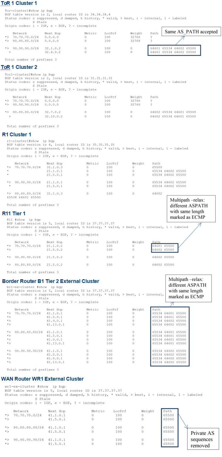
Validation
Use the show ip bgp command to validate the output at each node.
Consider the following case: for application load balancing and high availability/reliability, two similar application servers can be placed at two clusters. For users accessing the application server through the Internet, the access to the server is load balanced and failure of one of the application servers does not impact the accessibility. The following is the output at various nodes for a subnet, such as:
- 70.70.70.1(application server) at ToR1 in cluster 1 and cluster 2
- 80.80.80.1at ToR 1 cluster 1
- 90.90.1at ToR 1 cluster 2
Conclusion
OcNOS with EBGP routing is a highly scalable, simple and flexible way of laying IP fabric in a data center.
The data center can be easily scaled for:
- Highercomputing needs by adding more
- Higherperformance and redundancy by adding more cores
- Higheruplink speeds by adding more external/edge
References
Use of BGP for routing in large scale data centers: https://tools.ietf.org/html/draft-ietf-rtgwg-bgp-routing-large-dc-09
Appendix A: Configuring the Data
Center through NetConf
This appendix shows how to configure a data center through NetConf. This section contains XML payloads which can be used by any NetConf client to send configurations to OcNOS devices.
The configurations below in XML are communicated via RPC messages from the NetConf client to the
NetConf server.
This document uses the yang-cli which is part of open source OpenYumaMaster which and is preinstalled on a ZebM-enabled OcNOS ONIE package as a NetConf client.
Pre-requisite
Refer to
Yangcli Operations section of the
NetConf User Guide and perform these operations first:
- EstablishConnection
- LoadModules
Once the above operations are complete, edit-config operation can be performed with XML payloads using
the command:
yangcli ocnos@Hostname> edit-config config=@/<path-to-xml-file>/<xml-file>.xml
Save the below xml payloads as an .xml file in any desired location. Make sure that each XML payload starts
with <vr xmlns=”<namespace>”> and ends with </vr>.
TOR (leaf node) TOR.xml
This table shows the XML to configure an IP address:
| XML Payload |
Description |
| <vr xmlns=”https://www.ipinfusion.com/CMLSchema/ ZebOS”> |
namespace of the ZebOS module |
| <vrId>0</vrId> |
Vrid |
| <interface>
<ifName>xe49</ifName>
<ipAddr>50.52.1.1/24</ipAddr>
</interface>
<interface>
<ifName>ge2</ifName>
<ipAddr>50.54.1.1/24</ipAddr>
</interface> |
Configure the interfaces which are connected to the
SPINE routers.
This payload configures the IP address of the
interfaces xe49 and ge2. |
| </vr> |
Close namespace for the ZebOS module |
This is an example of the XML payload to be sourced in the yang CLI to configure an interface IP addresses:
<vr xmlns=”
https://www.ipinfusion.com/CMLSchema/ZebOS”>
<vrId>0</vrId>
<interface>
<ifName>xe49</ifName>
<ipAddr>50.52.1.1/24</ipAddr>
</interface>
<interface>
<ifName>ge2</ifName>
<ipAddr>50.54.1.1/24</ipAddr>
</interface>
</vr>
This table shows the XML to configure BGP attributes:
| XML Payload |
Description |
| <vr xmlns=”https://www.ipinfusion.com/CMLSchema/ ZebOS”> |
Namespace of the ZebOS module |
| <vrId>0</vrId> |
Enter Vrid |
| <bgp>
<bgpAs>64602</bgpAs> |
Open BGP tag.
Configure the BGP AS number. |
| <multipathRelax>1</multipathRelax>
<vrfName>default</vrfName> |
Configure “as-path multipath-relax” to
relax the AS-PATH criteria for BGP ECMP |
| <multipath>
<bgpType>ebgp</bgpType>
<multipathType>
<multipathsNum>8</ multipathsNum>
</multipathType>
</multipath> |
Configure maximum EBGP ECMP that can be
installed in BGP. |
| <bgpPeer>
<peerAddr>50.52.1.2</peerAddr>
<allowAsNum>3</allowAsNum>
<bgpPeerBfd>1</bgpPeerBfd>
<peerAs>64902</peerAs>
</bgpPeer> |
Configure BGP peer with AS 64902 and peer
address 50.52.1.2
Enable BFD for link failure detection
Configure “allowas” in for the neighbor to accept routes with same ASN learned over this neighbor |
| <bgpPeer>
<peerAddr>50.54.1.2</peerAddr>
<allowAsNum>3</allowAsNum>
<bgpPeerBfd>1</bgpPeerBfd>
<peerAs>64902</peerAs>
</bgpPeer> |
Configure BGP peer with AS 64902 and peer
address 50.54.1.2
Configure “allowas” in for the neighbor to accept routes with same ASN learned over this neighbor
Enable BFD for link failure detection. |
| <bgpRedistList>
<redistType>connected</redistType>
</bgpRedistList>
<bgpRedistList>
<redistType>ospf</redistType>
</bgpRedistList> |
Redistribute the connected and OSPF routes |
| </bgp> |
Close BGP tag. |
| </vr> |
Close namespace for the ZebOS module |
This table shows the XML to configure IP addresses:
| XML Payload |
Description |
| <vr xmlns=”https://www.ipinfusion.com/CMLSchema/ZebOS”> |
Enter namespace of the ZebOS module |
| <vrId>0</vrId> |
Enter Vrid |
| <interface>
<ifName>xe49/1</ifName>
<ipAddr>50.52.1.2/24</ipAddr>
</interface>
<interface>
<ifName>xe49/2</ifName>
<ipAddr>52.31.1.1/24</ipAddr>
</interface> |
Configure the interfaces which are connected
to the SPINE routers.
This payload configures the IP address of the
interfaces xe49/1 and xe49/2. |
| </vr> |
Close namespace for the ZebOS module |
This table shows the XML to configure BGP attributes:
| XML Payload |
Description |
| <vr xmlns=”https://www.ipinfusion.com/CMLSchema/ZebOS”> |
Enter namespace of the ZebOS module |
| <vrId>0</vrId> |
Enter Vrid |
| <bgp>
<bgpAs>64902</bgpAs> |
Open BGP tag.
Configure the BGP AS number. |
| <multipathRelax>1</multipathRelax>
<vrfName>default</vrfName> |
Configure “as-path multipath-relax” to relax the
AS-PATH criteria for BGP ECMP |
| <multipath>
<bgpType>ebgp</bgpType>
<multipathType>
<multipathsNum>8</multipathsNum>
</multipathType>
</multipath> |
Configure maximum EBGP ECMP that can be
installed in BGP. |
| <bgpRedistList>
<redistType>connected</redistType>
</bgpRedistList> |
Redistribute the connected routes |
| <bgpPeer>
<peerAddr>50.52.1.1</peerAddr>
<bgpPeerBfd>1</bgpPeerBfd>
<peerAs>64601</peerAs>
</bgpPeer> |
Configure BGP peer with AS 64602 and peer
address 50.52.1.1
Enable BFD for link failure detection. |
| <bgpPeer>
<peerAddr>52.31.1.2</peerAddr>
<bgpPeerBfd>1</bgpPeerBfd>
<peerAs>65501</peerAs>
</bgpPeer> |
Configure BGP peer with AS 65501 and peer
address 52.31.1.2
Enable BFD for link failure detection. |
| </bgp> |
Close BGP tag. |
| </vr> |
Close namespace for the ZebOS module |
This table shows the XML to configure IP addresses:
| XML Payload |
Description |
| <vr xmlns=”https://www.ipinfusion.com/CMLSchema/ZebOS”> |
Enter namespace of the ZebOS module |
| <vrId>0</vrId> |
Enter Vrid |
| <interface>
<ifName>xe1</ifName>
<linkStatus>1</linkStatus>
<ipLabel>NULL</ipLabel>
<ipAddr>52.31.1.2/24</ipAddr>
</interface>
<interface>
<ifName>ge8</ifName>
<linkStatus>0</linkStatus>
<ipLabel>NULL</ipLabel>
<ipAddr>31.22.1.1/24</ipAddr>
</interface> |
Configure the interfaces that are connected to
the spine routers.
This payload configures the IP address of the
interfaces xe1 and ge8. |
| </vr> |
Close namespace for the ZebOS module |
This table shows the XML to configure BGP attributes:
| XML Payload |
Description |
| <vr xmlns=”https://www.ipinfusion.com/CMLSchema/ZebOS”> |
Enter namespace of the ZebOS module |
| <vrId>0</vrId> |
Enter Vrid |
| <bgp>
<bgpAs>65501</bgpAs> |
Open BGP tag.
Configure the BGP AS number. |
| <multipathRelax>1</multipathRelax>
<vrfName>default</vrfName> |
Configure “as-path multipath-relax” to relax
the AS-PATH criteria for BGP ECMP |
| <multipath>
<bgpType>ebgp</bgpType>
<multipathType>
<multipathsNum>8</multipathsNum>
</multipathType>
</multipath> |
Configure maximum EBGP ECMP that can
be installed in BGP. |
| <bgpRedistList>
<redistType>connected</redistType>
</bgpRedistList> |
Redistribute the connected routes |
| <bgpPeer>
<peerAddr>52.31.1.1</peerAddr>
<bgpPeerBfd>1</bgpPeerBfd>
<peerAs>64902</peerAs>
</bgpPeer> |
Configure BGP peer with AS 64902 and peer
address 52.31.1.1
Enable BFD for link failure detection. |
| <bgpPeer>
<peerAddr>31.22.1.2</peerAddr>
<bgpPeerBfd>1</bgpPeerBfd>
<peerAs>65503</peerAs>
</bgpPeer> |
Configure BGP peer with AS 65503 and peer
address 31.22.1.2
Enable BFD for link failure detection. |
| </bgp> |
Close BGP tag. |
| </vr> |
Close namespace for the ZebOS module |
This table shows the XML to configure IP addresses:
| XML Payload |
Description |
| <vr xmlns=”https://www.ipinfusion.com/CMLSchema/ZebOS”> |
Enter namespace of the ZebOS module |
| <vrId>0</vrId> |
Enter Vrid |
| <interface>
<ifName>ge7</ifName>
<ipAddr>53.22.1.2/24</ipAddr>
</interface>
<interface>
<ifName>ge6</ifName>
<ipAddr>31.22.1.2/24</ipAddr>
</interface>
<interface>
<ifName>ge2</ifName>
<ipAddr>23.22.1.1/24</ipAddr>
</interface> |
Configure the interfaces which are connected
to the SPINE routers.
This payload configures the IP address of the
interface ge7, ge6 and ge2. |
| </vr> |
Close namespace for the ZebOS module |
This table shows the XML to configure BGP attributes:
| XML Payload |
Description |
| <vr xmlns=”https://www.ipinfusion.com/CMLSchema/ZebOS”> |
Enter namespace of the ZebOS module |
| <vrId>0</vrId> |
Enter Vrid |
| <bgp>
<bgpAs>65503</bgpAs> |
Open BGP tag
Configure the BGP AS number. |
| <multipathRelax>1</multipathRelax>
<vrfName>default</vrfName> |
Configure “as-path multipath-relax” to relax
the AS-PATH criteria for BGP ECMP |
| <multipath>
<bgpType>ebgp</bgpType>
<multipathType>
<multipathsNum>8</multipathsNum>
</multipathType>
</multipath> |
Configure maximum EBGP ECMP that can be
installed in BGP. |
| <bgpRedistList>
<redistType>connected</redistType>
</bgpRedistList> |
Redistribute the connected routes |
| <bgpPeer>
<peerAddr>53.22.1.1</peerAddr>
<bgpPeerBfd>1</bgpPeerBfd>
<peerAs>64902</peerAs>
</bgpPeer> |
Configure BGP peer with AS 64902 and peer
address 52.31.1.1
Enable BFD for link failure detection. |
| <bgpPeer>
<peerAddr>31.22.1.2</peerAddr>
<bgpPeerBfd>1</bgpPeerBfd>
<peerAs>65503</peerAs>
</bgpPeer> |
Configure BGP peer with AS 65503 and peer
address 31.22.1.2
Enable BFD for link failure detection. |
| <bgpPeer>
<peerAddr>23.22.1.2</peerAddr>
<bgpPeerBfd>1</bgpPeerBfd>
<peerAs>65502</peerAs>
<peerRemovePvtAs>1</peerRemovePvtAs>
</bgpPeer> |
Configure BGP peer with AS 65502 and peer
address 23.22.1.2
Enable BFD for link failure detection.
Configure remove-private-as for 23.22.1.2 peer |
| </bgp> |
Close BGP tag. |
| </vr> |
Close namespace for the ZebOS module |
This table shows the XML to configure an IP address:
| XML Payload |
Description |
| <vr xmlns=”https://www.ipinfusion.com/CMLSchema/ZebOS”> |
Enter namespace of the ZebOS module |
| <vrId>0</vrId> |
Enter Vrid |
| <interface>
<ifName>ge1/1/1</ifName>
<ipAddr>22.23.1.2/24</ipAddr>
</interface> |
Configure the interfaces that are connected to
the SPINE routers.
This payload configures the IP address of the
interface ge1/1/1. |
| </vr> |
Close namespace for the ZebOS module |
This table shows the XML to configure BGP attributes:
| XML Payload |
Description |
| <vr xmlns=”https://www.ipinfusion.com/CMLSchema/ZebOS”> |
Enter namespace of the ZebOS module |
| <vrId>0</vrId> |
Enter Vrid |
| <bgp>
<bgpAs>65502</bgpAs> |
Open BGP tag
Configure the BGP AS number. |
| <bgpRedistList>
<redistType>connected</redistType>
</bgpRedistList> |
Redistribute the connected routes |
| <bgpPeer>
<peerAddr>22.23.1.1</peerAddr>
<bgpPeerBfd>1</bgpPeerBfd>
<peerAs>65503</peerAs>
</bgpPeer> |
Configure BGP peer with AS 64902 and peer
address 52.31.1.1
Enable BFD for link failure detection. |
| </bgp> |
Close BGP tag. |
| </vr> |
Close namespace for the ZebOS module |
Appendix B: NetConf User Guide
This document describes managing OcNOS devices using NetConf.
This document is intended for network administrators and other engineering professionals who configure and
manage devices running OcNOS.
There are three different northbound applications in OcNOS (CLI , NetConf, and SNMP). All the northbound
applications are text-based, with each command usually associated to a specific task.
OcNOS NetConf supports transactions as described in
Transactions.
NetConf Quick Start
The NetConf protocol defines a simple mechanism through which a network device can be managed, configuration information can be retrieved, and new configuration data can be uploaded.
NetConf uses a simple RPC-based mechanism to communicate between a client and a server. The client can be a script or application typically running as part of a network manager. The server is usually a network device.
A NetConf session is the logical connection between a network administrator or network configuration application
and a network device. A device must support at least one NetConf session and can support multiple sessions. Global configuration attributes can be changed during any session and the effects are visible in all sessions. The candidate and running and startup configuration are shared across all the sessions.
Note: A limited number of protocol modules are supported through NetConf. A detailed list is in the NetConf command reference.
NetConf Clients
You can use any NetConf client application to manage the device using Yang modules. These client applications require a Yang module which you downlaod from:
https://github.com/IPInfusion/OcNOS/tree/1.2
This application establishes a secure connection with the daemon running on the device to perform commands and send system responses.
There are different NetConf client applications. In this document, OpenYuma’s yangcli application is used to show NetConf operations.
Refer to the standard Yangcli operations at:
https://github.com/OpenClovis/OpenYuma/blob/master/netconf/doc/yuma_docs/openyuma-yangcli-manual.odt
The NetConf operations get-config and get return large amounts of data. To improve the readability of the output, the subtree filter based sget-config and sget operations are used in this document.
Install Yangcli
Check out the git
repository, compile and install OpenYuma components. Refer to the
README for more details.
Download Yang files
Download the Yang files from the website:
https://github.com/IPInfusion/OcNOS/tree/1.2
Copy the files to /usr/share/yuma/modules/netconfcentral on the host machine where the client application runs. This system path only works with OpenYuma’s Yangcli client application. If you are running a different client application, follow the respective reference document to copy the Yang files to the appropriate location.
Creating User Accounts
User level access control applies to all NetConf operations. The table below describes access levels for different user types and commands to create different type of user account
| Account type |
Access |
Command |
| User |
Read |
username <user name> role network-user password
<password> |
| Operator |
All, except full configuration store
level change. |
username <user name> role network-operator password <password> |
| Admin |
All |
username <user name> role network-admin password
<password> |
You must login into the device using network administrator account to create new user accounts. These are the steps:
[root@localhost ~]# ssh
ocnos@10.12.45.253 ocnos@10.12.45.253’s password:
Last login: Wed Jun 15 21:27:39 2016
OcNOS version 1.2.0.179-OCNOS-DC-IPBASE-ZEBM IPIRouter 06/14/16 21:30:36
OcNOS>en
OcNOS#configure terminal
Enter configuration commands, one per line. End with CNTL/Z. OcNOS(config)#username netuser role network-user password Abc@6789 OcNOS(config)#username netoperator role network-operator password Abc@6789 OcNOS(config)#username netadmin role network-admin password Abc@6789
After creating the account, use the write command to write the configured data into persistent storage as
described in
Copy Running Configuration to Startup
OcNOS(config)#write Building configuration… [OK]
The NetConf operations for different user account types are shown in
Supported Operations.
Yangcli Operations
Establish Connection
These are the steps to establish a connection between the NetConf client and the server that is running on the device.
# yangcli server=<ip _ address> user=<user _ name> password=<password> ip _ address: Address of the device to be managed
user _ name & password: User account detail for authentication
The interactive version of this command is shown below:
# yangcli yangcli> connect
Enter string value for leaf <user> yangcli:connect> <user _ name>
Enter string value for leaf <server> yangcli:connect> <ip _ address>
Enter string value for leaf <password> yangcli:connect> <password>
Load Modules
The load command loads a YANG module into the server. This command is not part of the RFC and is only supported by the Yang client.
The ZebOS module is the parent for all protocol modules supported in OcNOS. This module includes all the sub modules. Therefore, loading this module is mandatory to start managing the device. Here is the portion of ZebOS.yang file that includes other sub modules.
module ZebOS {
namespace “
https://www.ipinfusion.com/CMLSchema/ZebOS”;
prefix “ZebOS”; include nsmLACP; include oamBfd;
…
}
include bridge; include ospf; include vlan; include mstp; include layer2LACP; include bgp; include vr;
include vrf; include interface; include lldpv2; include ospf6; include rib;
include vlaninterface;
> load ZebOS
RPC Data Reply 1 for session 1:
rpc-reply {
mod-revision 2015-10-08
}
After using the load command, you can also use the mgrload command to keep the current session synchronized with the server.
> mgrload ZebOS
Load module ‘ZebOS’ OK
Configure the Device
Configuration details are placed in an XML file and sent to the netconfd server. You must refer to the Yang file to prepare the XML based configuration file with the correct hierarchy. If the hierarchy is not correct, yangcli throws an error.
One portion of the BGP protocol module Yang model is presented below. This module is a sub-module for the parent ZebOS yang module.
submodule bgp {
belongs-to ZebOS { prefix ZebOS; } include interface;
include vrf;
import cml _ data _ types { prefix cml _ data _ types;
}
revision “2015-04-25” {
description “Revised on 2015-04-25.”; }
grouping bgp-grouping { list bgp {
description “bgp”; config true;
key “bgpAs”; leaf vrId {
mandatory false; type leafref {
path “/vr/vrId”;
…
}
} // END of vrId definition.
leafkeepAlive { mandatory false;
type cml _ data _ types:CML _ UINT16 _ T { range “0..65535”;
}
default “30”; config true;
} // END of keepAlive definition.
leafholdTime { mandatory false;
type cml _ data _ types:CML _ UINT16 _ T { range “0..65535”;
…
}
default “90”; config true;
} // END of holdTime definition.
} // END of bgpDebug-grouping definition.
Based on the hierarchy in the Yang module. the following XML file named bgp.xml is created with the configuration data. The bgp.xml file is referenced in the edit-config operation specified below.
<vr xmlns=”
https://www.ipinfusion.com/CMLSchema/ZebOS”>
<vrId>0</vrId>
<bgp>
<bgpAs>100</bgpAs>
<keepAlive>60</keepAlive>
<holdTime>180</holdTime>
</bgp>
</vr>
Use this command to globally set or reset the keepalive and holdtime values for all the neighbors.
yangcli
ocnos@10.12.45.253> edit-config config=@/root/bgp.xml Filling container /edit-config/input/target:
RPC OK Reply 15 for session 1:
Retrieve Candidate Configuration
Candidate configuration datastore is used to hold configuration data that can be manipulated without impacting the device’s current configuration. The candidate configuration is a full configuration data set that serves as a work place for creating and manipulating configuration data. Additions, deletions, and changes can be made to this data to construct the desired configuration data.
>sget-config /vr/bgp source=candidate Filling list /vr/bgp:
RPC Data Reply 1 for session 2:
rpc-reply { data {
vr {
bgp 100 {
bgpAs 100
holdTime 180
keepAlive 60 vrfName default
}
}
}
}
Commit Candidate Configuration
A <commit> operation MAY be performed at any time that causes the device’s running configuration to be set to the value of the candidate configuration.
yangcli
ocnos@10.12.45.253> commit RPC OK Reply 16 for session 1:
Retrieve Running Configuration
Configuration data is the set of writable data that is required to transform a system from its initial default state into its current state. You can use the get-config operation to fetch the running configuration data.
>sget-config /vr/bgp source=running Filling list /vr/bgp:
RPC Data Reply 1 for session 2:
rpc-reply { data {
vr {
bgp 100 {
bgpAs 100
holdTime 180
keepAlive 60 vrfName default
}
}
}
}
Retrieve Running Configuration and State Data
State data is the additional data on a system that is not configuration data such as read-only status information and collected statistics. You can use the get operation to fetch a protocol module’s running configuration and state data.
>sget /vr/bgp rpc-reply {
data { vr {
bgp 100 {
bgpAs 100
holdTime 180
keepAlive 60 vrfName default bgpTableVersion 0
ntwkPrefixCount 0
ibgpMetric 0
pathAttrBest 0 clusterList fill _ value
routerRunIpAddr fill _ value bgpShowTypeStr fill _ value bgpShowType 0
rfdMaxPenaltyCeil 0
rfdMinPenaltyFloor 0
dampeningStr 0
rfdCbStr 0
ibgpMetric 0
}
}
}
}
Copy Running Configuration to Startup
NetConf supports startup options, so if you have configured the device and want to retain the configuration after a device reboot, copy the running configuration into startup configuration. The yangcli command is:
> copy-config source=running target=startup The equivalent OcNOS command is
# write
Error Messages
NetConf operations return protocol, management layer, and protocol module errors. The example below depicts an error returned by a protocol module.
Copy the content below into bgp_err.xml.
<vr xmlns=”
https://www.ipinfusion.com/CMLSchema/ZebOS”>
<vrId>0</vrId>
<bgp>
<bgpAs>1</bgpAs>
<keepAlive>300</keepAlive>
<holdTime>200</holdTime>
</bgp>
</vr>
Execute the following command and commit the changes
yangcli
tbyran@10.12.45.253> edit-config config=@/root/bgp _ err.xml Filling container /edit-config/input/target:
RPC OK Reply 12 for session 1: yangcli
tbyran@10.12.45.253> commit
mgr _ rpc: got invalid reply on session 1 (invalid XPath expression syntax) RPC Error Reply 13 for session 1:
rpc-reply { rpc-error {
error-type protocol error-tag
error-severity warning
error-app-tag general-warning error-path ‘RPC operation failed’
error-message ‘%% Hold time should be greater than the keepalive time’ error-info {
error-number 4294962411
}
}
}
Transactions
OcNOS supports transaction-oriented configuration management. Transactions are created implicitly by edit- config operations; commit and discard-changes operations close or terminate the transactions. Successive edit-config operations are placed in the same transaction.
Discard Changes
Discard the transaction or candidate configuration changes.
yangcli
ocnos@10.12.45.253> sget-config /vr/ospf source=candidate Filling list /vr/ospf:
mgr _ rpc: got invalid reply on session 1 (missing index component) RPC Data Reply 14 for session 2:
rpc-reply { data {
vr {
ospf 0 {
ospfProcessId 0 ospfShutDown true
}
ospf 200 {
ospfProcessId 200
}
}
}
}
yangcli
ocnos@10.12.45.253> discard-changes RPC OK Reply 15 for session 2:
yangcli
ocnos@10.12.45.253> sget-config /vr/ospf source=candidate Filling list /vr/ospf:
mgr _ rpc: got invalid reply on session 1 (missing index component) RPC Data Reply 16 for session 2:
rpc-reply { data {
vr {
ospf 0 {
ospfProcessId 0 ospfShutDown true
}
}
}
}
Commit
Commit the transaction or candidate configuration changes.
yangcli
ocnos@10.12.45.253> create /vr/ospf
Filling list /vr/ospf:
Filling key leaf /vr/ospf/ospfProcessId: Enter int32 value for leaf <ospfProcessId> yangcli ocnos@10.12.45.253:create> 500
Filling key leaf /vr/vrId:
Enter uint32 value for leaf <vrId> yangcli
ocnos@10.12.45.253> 0
RPC OK Reply 17 for session 2: yangcli
ocnos@10.12.45.253> commit RPC OK Reply 18 for session 2:
yangcli
ocnos@10.12.45.253> sget-config /vr/ospf source=running Filling list /vr/ospf:
mgr _ rpc: got invalid reply on session 1 (missing index component) RPC Data Reply 19 for session 2:
rpc-reply { data {
vr {
ospf 0 {
ospfProcessId 0 ospfShutDown true
}
ospf 500 {
ospfProcessId 500
}
}
}
}
Save Point
OcNOS supports the savepoint feature. A savepoint is a snapshot of the device current state. You can switch the device state to any savepoint at any time.
This example creates two savepoints HT180 and HT300
- HT180has holdTime set to 180
- HT300has holdTime set to 300
yangcli
ocnos@10.12.45.253> create
create create-savepoint create-subscription yangcli
ocnos@10.12.45.253> create-savepoint
Enter string value for leaf <savepointName> yangcli ocnos@10.12.45.253:create-savepoint> HT180
RPC OK Reply 4 for session 2:
yangcli
ocnos@10.12.45.253> edit-config config=@/root/bgp _ ht.xml Filling container /edit-config/input/target:
RPC OK Reply 5 for session 2: yangcli
ocnos@10.12.45.253> commit RPC OK Reply 6 for session 2:
yangcli
ocnos@10.12.45.253> sget-config /vr/bgp source=running
Filling list /vr/bgp:
mgr _ rpc: got invalid reply on session 1 (missing index component) RPC Data Reply 7 for session 2:
rpc-reply { data {
vr {
bgp 100 {
bgpAs 100
holdTime 300
keepAlive 60
vrfName default
}
}
}
}
yangcli
ocnos@10.12.45.253> create-savepoint HT300 RPC OK Reply 8 for session 2:
Roll Back
This example shows rolling back the configuration. First, notice the current value of the holdTime attribute:
yangcli
ocnos@10.12.45.253> sget-config /vr/bgp source=running
Filling list /vr/bgp:
mgr _ rpc: got invalid reply on session 1 (missing index component) RPC Data Reply 10 for session 2:
rpc-reply { data {
vr {
bgp 100 {
bgpAs 100
holdTime 180
keepAlive 60 vrfName default
}
}
}
}
Now roll back to savepoint HT300 and note the value of holdTime attribute.
yangcli
ocnos@10.12.45.253> rollback-transaction HT300 RPC OK Reply 11 for session 2:
yangcli
ocnos@10.12.45.253> sget-config /vr/bgp source=running
Filling list /vr/bgp:
mgr _ rpc: got invalid reply on session 1 (missing index component) RPC Data Reply 12 for session 2:
rpc-reply { data {
vr {
bgp 100 {
bgpAs 100
holdTime 300
keepAlive 60 vrfName default
}
}
}
}
Supported Operations
All the NetConf operations are captured based on the capability. Hence, any operation falling in multiple
capability are documented separately.
Note: Capability “base:1.0” supports candidate and running configuration store.
| Capability |
Operation |
User Role |
Supported (Yes/No) |
Comments |
| :base:1.0 |
<get> |
User, Operator, Admin |
Yes |
|
| :base:1.0 |
<get> with subtree filter |
User, Operator, Admin |
Yes |
|
| :base:1.0 |
<get-config> |
User, Operator, Admin |
Yes |
|
| :base:1.0 |
get-config source=<target> |
User, Operator, Admin |
Yes |
|
| :base:1.0 |
<get-config> with subtreefilter |
User, Operator, Admin |
Yes |
|
| :base:1.0 |
<edit-config> <target> as parameter |
Operator, Admin |
Yes |
Running configuration as target is not supported because writtable- running capability is not supported |
| :base:1.0 |
<edit-config> <config> as parameter |
Operator, Admin |
Yes |
|
| :base:1.0 |
<edit-config>:
<merge> |
Operator, Admin |
Yes |
|
| :base:1.0 |
<edit-config>:
<replace> |
Operator, Admin |
Yes |
|
| :base:1.0 |
<edit-config>:
<create> |
Operator, Admin |
Yes |
|
| :base:1.0 |
<edit-config>:
<delete> |
Operator, Admin |
Yes |
|
| :base:1.0 |
<edit-config>:
<remove> |
Operator, Admin |
Yes |
|
| Capability |
Operation |
User Role |
Supported (Yes/No) |
Comments |
| :base:1.0 |
<edit-config>: <none> |
Operator, Admin |
Yes |
|
| :base:1.0 |
<edit-config>: <error- option > as stop-on- error |
Operator, Admin |
No |
|
| :base:1.0 |
<edit-config>: <error- option > as continue- on-error |
Operator, Admin |
No |
|
| :rollback-on- error:1.0 |
<edit-config>: <error- option > as rollback- on-error |
Operator, Admin |
Partial |
By default, this is the behavior. So there is no need to pass this error- option. |
| :validate: 1.1 |
<edit-config>: <test- option > |
Operator, Admin |
No |
By default configuration entries are validated and stored, hence
this operation and its parameters are not handled. External configuration store validation is not supported (i.e URL). |
| :base:1.0 |
<copy-config> : < target> <source> |
Operator, Admin |
Yes |
|
| :base:1.0 |
<lock> : < target> |
Operator, Admin |
Yes |
Candidate configuration
lock is not supported. |
| :base:1.0 |
<unlock> : < target> |
Operator, Admin |
Yes |
Candidate configuration
unlock is not supported |
| :base:1.0 |
<close-session> close current session |
User, Operator, Admin |
Yes |
|
| :base:1.0 |
<kill-session> : Close other session |
User, Operator, Admin |
Yes |
|
| :base:1.0 |
subtreefiltering |
User, Operator, Admin |
Yes |
|
| :Startup:1.0 |
get-config
<source=startup> |
User, Operator, Admin |
Yes |
|
| :Startup:1.0 |
copy-config
<source=startup> |
Admin |
No |
|
| :Startup:1.0 |
copy-config
<target=startup> |
Admin |
Partial |
Running to startup copy is supported. |
| :Startup:1.0 |
lock <startup> |
Admin |
Yes |
|
| :Startup:1.0 |
unlock <startup> |
Admin |
Yes |
|
| Capability |
Operation |
User Role |
Supported (Yes/No) |
Comments |
| :Startup:1.0 |
validate
<source=startup> |
Admin |
No |
Always configuration entries are validated and stored, but external configuration store validation is not supported. |
| :Startup:1.0 |
delete-config |
Admin |
Yes |
|
| :url:1.0 |
URL capability |
User, Operator, Admin |
No |
Not supported |
| :with-defaults |
<get> |
User, Operator, Admin |
Partial |
By default, “report-all” functionality is supported when with-default
option is passed. Other options (explicit, tagged, explicit-tagged) are not supported |
| :with-defaults |
<get-config> |
User, Operator, Admin |
Partial |
By default, “report-all” functionality is supported when with-default
option is passed. Other options (explicit, tagged, explicit-tagged) are not supported |
| :confirmed- commit |
<commit> <confirmed> |
Operator, Admin |
Yes |
|
| :confirmed- commit |
<commit> <confirmed>
<persist> |
Operator, Admin |
Yes |
|
For more information:
Data Center Solution – EVPN with VXLAN
CHAPTER 1
Data Center Solution Overview
Data Center Virtualization
Virtualization Technologies
Data Center Virtualization with VXLAN and EVPN
CHAPTER 2
VXLAN and EVPN Overview
OcNOS VXLAN EVPN Architecture
VXLAN using Unicast and Multicast Tunnels
EVPN Learns VTEP Topology
Basic Example Configuration
- Non-EVPN: VXLANUnicast Traffic 8
- EVPN:VXLAN with EVPN Control Plane 11
- Non-EVPN:VXLAN with Data Plane Learning 16
- EVPN:VXLANTenant Identification using Port and VLAN 20
Conclusion 24
Glossary
VXLAN – Virtual extensible LAN
EVPN – Ethernet Virtual Private Network VM – Virtual Machine
PBB – Provider Backbone bridging OTV – Overlay Transport Virtualization
NVGRE – Network virtualization using Generic Route Encapsulation MPLS – Multiprotocol Label Switching
VPLS – Virtual Private LAN Service STT – Stateless Transport Tunelling
ISIS – Intermediate system – Intermediate system BGP – Border Gateway Protocol
MP-BGP – Multiprotocol Border Gateway Protocol
CHAPTER 1
Data Center Solution Overview
- DataCenter Virtualization
- VirtualizationTechnologies
- DataCenter Virtualization with VXLAN and EVPN
Data Center Virtualization
With the increase of data centers and huge amount of data that they store and manage and the increase in services, virtualization in data canters has been the need of the day. Server virtualization helps in reducing the cost to setup and manage a data center, as not only does it reduces the cost in buying and setting up the hardware, it also reduces the cost for cooling, electricity and maintenance. Also, most enterprise data centers are deployed in a hybrid cloud environment, which require the ability to expand, reduce or move their services/virtual machines.
Redeploying a service or a VM, needs support from the data center network. When new VMs have to be added in a data center or old VMs need to be moved, they should be added based on the compute availability and not because of the network configuration for the customer. This way the compute infrastructure is better utilized. In IP networks this requires reconfiguration of L3 infrastructure or a change in the customer VM IP address. This is not acceptable in a data center deployment. Tenants would want their VMs in the same subnet, wherever they are placed.
An overlay protocol can be used to connect the customer virtual machines (VMs) on servers located at different locations in the network to communicate without affecting the L3 infrastructure. The following sections discuss the technologies that can be used for this purpose.
Virtualization Technologies
An overlay is basically a tunneling protocol where the customer traffic can be tunneled across the network, without reconfiguring the network. Various tunneling technologies are in use in the enterprise and data center network.
- Q-in-Qtunneling or provider bridging provides a solution to scale beyond the 4K VLAN limitation, but it does not hide the customer MAC addresses from the core
PBB or Mac-in-Mac tunneling provided a solution to hide customer MAC addresses along with scaling, but it has a disadvantage on relying on xSTP protocols.
TRILL and SPB solved the issue of reliance on STP by using ISIS control plane learning. These technologies are deployable at the edge networks.
OTV and LISP are other tunneling technologies which address L2/L3 over L3 networks.
MPLS based VPLS and VPRN services provide VPN services within the data center and data center interconnect.
New host based virtualization technologies focus more on VM/Service mobility and multitenancy.
VXLAN, NVGRE and STT are some of the technologies developed in this area. VXLAN is the most popular among these as it is an UDP-based protocol allowing the network to use multiple paths. In this paper, VXLAN and EVPN will be discussed in details.
Data Center Virtualization with VXLAN and EVPN
VXLAN, NVGRE and STT are some of the technologies developed in this area. VXLAN is the most popular amongst these as it is an UDP based protocol providing the network to use multipaths. In this paper, VXLAN and EVPN will be discussed in details.
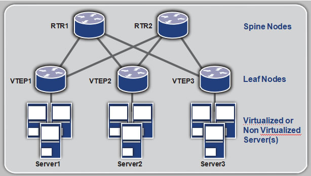
The VTEPs (Virtual Tunnel Endpoints) form UDP tunnels among themselves. VTEPs identify a specific tenant’s traffic and encapsulate it within the UDP tunnel. If the traffic is broadcast, multicast or unknown, then the traffic is multicasted over UDP to other VTEPs. A VXLAN header is inserted by the VTEP to identify the tenant of the traffic.
OcNOS supports VTEP functionality for VXLAN tunnels.
VXLAN depends on multicast and data plane learning to discover the VTEPs. To overcome this limitation, OcNOS supports EVPN control plane for VXLAN from Release 1.1 as beta quality.
EVPN is a control plane technology using MP-BGP for implementing VPN technologies in a network. EVPN was developed to provide the following improvements over the current VPN technologies.
- Controlplane learning
- Multicastoptimization
- Multihoming
- Simplicityin provisioning
- Achievingvarious services
- Betterreconvergence
When VXLAN is deployed in DCI, multicast and data plane learning are not preferred. A VXLAN solution with EVPN control plane is preferred in that deployment.
The next chapter describes the VXLAN and EVPN solution in OcNOS.
CHAPTER 2
VXLAN and EVPN Overview
- OcNOSVXLAN EVPN architecture
- VXLANusing unicast and multicast tunnels
- EVPNto learn VTEP topology
- Basic exampleconfigurations
OcNOS VXLAN EVPN Architecture
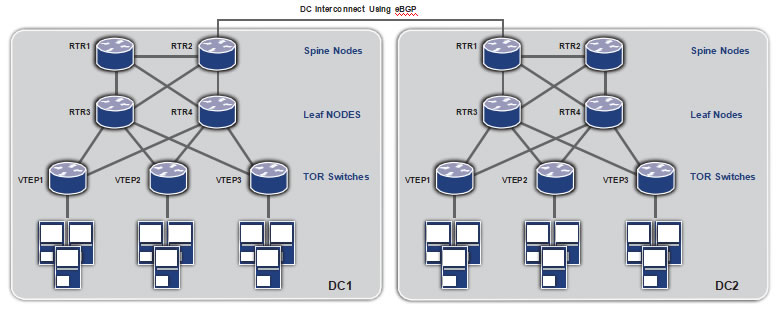 DC Interconnect Using eBGP
The above topology diagram demonstrates the network architecture which will be used to describe this solution. The access or top-of-rack (TOR) switches) implement the VTEP functionality. The Leaf node routers act as Route Reflectors and communicate within the data center. The Spine node routers act as second-level hierarchical Route Reflectors to communicate between different data centers using eBGP on the data center interconnect (DCI). MP-BGP is used at the routers and VTEPs to implement EVPN.
VXLAN using Unicast and Multicast Tunnels
VXLAN technology is defined in RFC 7348. The OcNOS implementation of VXLAN complies with the specification. In addition to providing the option of IP multicast for broadcast, unknown and multicast (BUM) traffic, the OcNOS implementation also provides an option for head-end replication of this kind of traffic.
This configuration shows a unicast-only VXLAN VNID (Tenant), mostly used for ELINE services. Also shown in this configuration is mapping a port to a tenant and a static entry for a remote virtual machine MAC address.
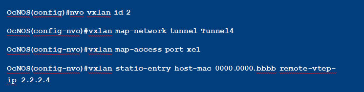
This configuration shows a VXLAN VNID with IP multicast tunnels. All broadcast, unknown and multicast traffic will be sent on the tunnel destined to the multicast IP address specified in the configuration.

This configuration shows a VXLAN VNID with head-end replication. All broadcast, unknown and multicast traffic will be sent on all the unicast tunnels mapped to this tenant, in this case on both Tunnel4 and Tunnel5.
The tenant traffic can be identified through a port or through a port+VLAN identifier mapped to the tenant.
When a port is mapped to the tenant, all traffic arriving at the port is treated as the tenant traffic and
tunneled to remote VTEP(s) using the tenant id (VNID) in the VXLAN header.
When a port+VLAN is mapped to the tenant, all traffic tagged with the specified VLAN arriving at the specified port is treated as the tenant traffic. When tunneled, the packet is encapsulated as shown in the below packet capture.
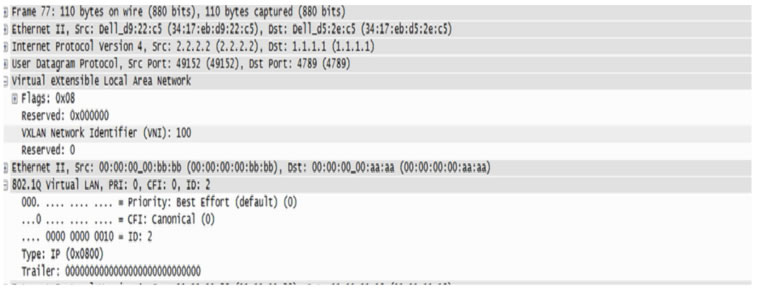
EVPN Learns VTEP Topology
EVPN was introduced in RFC 7432 for VPLS. EVPN was then extended for overlay technologies like VXLAN in draft-ietf-bess-evpn-overlay-02. The OcNOS EVPN solution complies with these standards. It is implemented only for the VXLAN data plane and is extensible to other data planes.
EVPN defines the use of MP-BGP protocol for learning the MAC/IP of the hosts connected to the VTEPs. The host MAC/IP is learned at the local VTEP through data plane learning. This is then transmitted to the other VTEPs through MP BGP. The remote VTEPs learn these routes at the tunnels connected to these VTEPs. The tunnels are learned automatically through MP-BGP.
In the configuration below, BGP neighbors are configured for the EVPN address family.

When configuring VXLAN VNIDs, it needs to be specified that EVPN will be used as a control plane. This is shown in the below configuration.
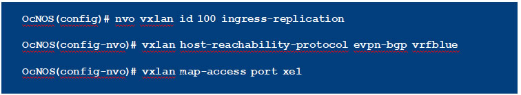
As can be seen in the above configuration, for VNIDs that will be using EVPN, there is no need to configure a tunnel, it will be automatically configured through BGP EVPN.
When a VNID is configured with EVPN, a BGP update message is sent to the EVPN neighbors with this information. This is the “Inclusive Multicast Ethernet Tag Route”. OcNOS supports only head end replication with EVPN. Once the tunnels are established on receiving this route, the MAC IP advertisements for host MAC and IP are distributed to the remote VTEPs using BGP-MP. This is
illustrated in the packet capture below. On receiving this route, the MAC/IP for the remote host is learned at this tunnel, and the packets will no longer be multicasted
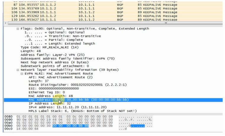
At the route reflectors, the neighbors are configured as RR clients for the EVPN address family. The hierarchical RRs help load balance the intra and inter data center traffic.
Basic Example Configuration
1. Non-EVPN: VXLAN Unicast Traffic
This configuration has the following features:
- Dataplane learning
- ISIS configured as interior gatewayprotocol
- Theloopback interface is used as the VTEP IP
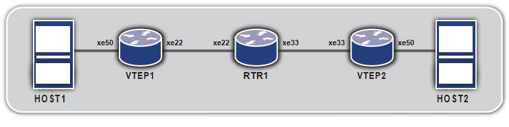
Topology
|
C om man d |
Purpose |
| Step 1 |
VTEP1#configure terminal |
Entering configuration mode |
| Step 2 |
VTEP1(con fi g)#bridge 1 protocol mstp |
Creating bridge |
| Step 3 |
VTEP1(con fi g)#interface xe50 |
Configure xe50 interface. |
| Step 4 |
VTEP1(con fi g-if)#switchport |
Configure the port as L2 port. |
| Step 5 |
V T E P 1 ( co n f i g – i f ) # b ri d g e – g ro u p 1 |
Add the port to the bridge |
| Step 6 |
VTEP1(con fi g-if)#switchport mode access |
Set the port as access port |
| Step 7 |
VTEP1(con fi g-if)#no shutdown |
Set interface state as up |
| Step 8 |
VTEP1(con fi g-if)#exit |
Exit interface mode |
| Step 9 |
VTEP1(con fi g)#interface xe22 |
Configure xe22 interface |
| Step 10 |
VTEP1(con fi g-if)#no switchport |
Configure the port as L3 port. |
| Step 11 |
VTEP1(con fi g-if)#ip address 11.11.11.1/24 |
Configure IP address on the interface |
| Step 12 |
VTEP1(con fi g-if)#no shutdown |
Set interface state as up |
| Step 13 |
VTEP1(con fi g-if)#exit |
Exit interface mode |
| Step 14 |
VTEP1(con fi g)#interface lo |
Configure loopback interface |
| Step 15 |
VTEP1(con fi g-if)#ip address 2.2.2.1/24 |
Configure IP address on the interface |
| Step 16 |
VTEP1(con fi g-if)#exit |
Exit interface mode |
| Step 17 |
VTEP1(con fi g)#router isis ipi |
Configure ISIS as IGP. |
| Step 18 |
VTEP1(con fi g-router)#is-type level-1 |
Set the ISIS as Level 1. |
| Step 19 |
VTEP1(con fi g-router)#net 49.0001.1111.1111.1111.00 |
Establish a Network Entity Title for this instance, specifying the area address and the system ID. |
| Step 20 |
VTEP1(con fi g-if)#exit |
Exit router mode |
| Step 21 |
VTEP1(con fi g)#interface lo |
Configure loopback interface |
| Step 22 |
VTEP1(con fi g-if)#ip router isis ipi |
Enable IS-IS routing on an interface for area ipi |
| Step 23 |
VTEP1(con fi g-if)#isis circuit-type level-1 |
Set the circuit type for the interface lo |
| Step 24 |
VTEP1(con fi g-if)#exit |
Exit interface mode |
| Step 25 |
VTEP1(con fi g)#interface xe22 |
Configure xe22 interface |
| Step 26 |
VTEP1(con fi g-if)#ip router isis ipi |
Enable IS-IS routing on an interface for area ipi |
| Step 27 |
VTEP1(con fi g-if)#isis circuit-type level-1 |
Set the circuit type for the interface xe22 |
| Step 28 |
VTEP1(con fi g-if)#exit |
Exit interface mode |
| Step 29 |
VTEP1(con fi g)#nvo vxlan enable |
Enable VXLAN. Configure the node as VTEP. |
| Step 30 |
VTEP1(con fi g)#interface tunnel 98 |
Configure Tunnel interface |
| Step 31 |
VTEP1(con fi g-if)#tunnel mode vxlan |
Set the tunnel interface for vxlan |
| Step 32 |
VTEP1(con fi g-if)#tunnel source 2.2.2.1 |
Set the tunnel source ip |
| Step 33 |
VTEP1(con fi g-if)#tunnel destination 3.3.3.1 |
Set the tunnel destination ip |
| Step 34 |
VTEP1(con fi g-if)#exit |
Exit interface mode |
| Step 35 |
VTEP1(con fi g)#nvo vxlan id 54321 ingress- replication |
Configure a VXLAN VPN with head end replication |
| Step 36 |
VTEP1(con fi g-nvo)#vxlan map-access port xe50 |
Set xe50 as access port to VPN 54321 |
| Step 37 |
V T E P 1 ( co n f i g – n v o ) # v x l a n m a p – n e t w ork t un n e l
Tunnel98 |
Set Tunnel98 as network tunnel for VPN 54321 |
| Step 38 |
VTEP2(con fi g-nvo)#vxlan static-entry host-mac
0000.0000.bbbb remote-vtep-ip 3.3.3.1 |
Add a static entry for remote host |
| |
C om man d |
Purpose |
| Step 1 |
VTEP2#configure terminal |
Entering configuration mode |
| Step 2 |
VTEP2(con fi g)#bridge 1 protocol mstp |
Creating bridge |
| Step 3 |
VTEP2(con fi g)#interface xe50 |
Configure xe50 interface. |
| Step 4 |
VTEP2(con fi g-if)#switchport |
Configure the port as L2 port. |
| Step 5 |
VTEP2(con fi g-if)#bridge-group 1 |
Add the port to the bridge |
| Step 6 |
VTEP2(con fi g-if)#switchport mode access |
Set the port as access port |
| Step 7 |
VTEP2(con fi g-if)#no shutdown |
Set interface state as up |
| Step 8 |
VTEP2(con fi g-if)#exit |
Exit interface mode |
| Step 9 |
VTEP2(con fi g)#interface xe33 |
Configure xe33 interface |
| Step 10 |
VTEP2(con fi g-if)#no switchport |
Configure the port as L3 port. |
| Step 11 |
VTEP2(con fi g-if)#ip address 12.12.12.1/24 |
Configure IP address on the interface |
| Step 12 |
VTEP2(con fi g-if)#no shutdown |
Set interface state as up |
| Step 13 |
VTEP2(con fi g-if)#exit |
Exit interface mode |
| Step 14 |
VTEP2(con fi g)#interface lo |
Configure loopback interface |
| Step 15 |
VTEP2(con fi g-if)#ip address 3.3.3.1/24 |
Configure IP address on the interface |
| Step 16 |
VTEP2(con fi g-if)#exit |
Exit interface mode |
| Step 17 |
VTEP2(con fi g)#router isis ipi |
Configure ISIS as IGP. |
| Step 18 |
VTEP2(con fi g-router)#is-type level-1 |
Set the ISIS as Level 1. |
| Step 19 |
VTEP2(con fi g-router)#net 49.0001.3333.3333.3333.00 |
Establish a Network Entity Title for this instance, specifying the area address and the system ID. |
| Step 20 |
VTEP2(con fi g-if)#exit |
Exit router mode |
| Step 21 |
VTEP2(con fi g)#interface lo |
Configure loopback interface |
| Step 22 |
VTEP2(con fi g-if)#ip router isis ipi |
Enable IS-IS routing on an interface for area ipi |
| Step 23 |
VTEP2(con fi g-if)#isis circuit-type level-1 |
Set the circuit type for the interface lo |
| Step 24 |
VTEP2(con fi g-if)#exit |
Exit interface mode |
| Step 25 |
VTEP2(con fi g)#interface xe33 |
Configure xe33 interface |
| Step 26 |
VTEP2(con fi g-if)#ip router isis ipi |
Enable IS-IS routing on an interface for area ipi |
| Step 27 |
VTEP2(con fi g-if)#isis circuit-type level-1 |
Set the circuit type for the interface xe33 |
| Step 28 |
VTEP2(con fi g-if)#exit |
Exit interface mode |
| Step 29 |
VTEP2(con fi g)#nvo vxlan enable |
Enable VXLAN. Configure the node as VTEP. |
| Step 30 |
VTEP2(con fi g)#interface tunnel 98 |
Configure Tunnel interface |
| Step 31 |
VTEP2(con fi g-if)#tunnel mode vxlan |
Set the tunnel interface for vxlan |
| Step 32 |
VTEP2(con fi g-if)#tunnel source 3.3.3.1 |
Set the tunnel source ip |
| Step 33 |
VTEP2(con fi g-if)#tunnel destination 2.2.2.1 |
Set the tunnel destination ip |
| Step 34 |
VTEP2(con fi g-if)#exit |
Exit interface mode |
| Step 35 |
VTEP2(con fi g)#nvo vxlan id 54321 ingress- replication |
Configure a VXLAN VPN with head end replication |
| Step 36 |
VTEP2(con fi g-nvo)#vxlan map-access port xe50 |
Set xe50 as access port to VPN 54321 |
| Step 37 |
VTEP2(con fi g-nvo)#vxlan map-network tunnel
Tunnel98 |
Set Tunnel98 as network tunnel for VPN 54321 |
| Step 38 |
VTEP2(con fi g-nvo)#vxlan static-entry host-mac
0000.0000.aaaa remote-vtep-ip 2.2.2.1 |
Add a static entry for remote host |
| |
C om man d |
Purpose |
| Step 1 |
RTR1#configure terminal |
Entering configuration mode |
| Step 2 |
RTR1(con fi g)#interface xe22 |
Configure xe22 interface. |
| Step 3 |
RTR1(con fi g-if)#no switchport |
Configure the port as L3 port. |
| Step 4 |
RTR1(con fi g-if)#ip address 11.11.11.2/24 |
Configure IP address on the interface |
| Step 5 |
RTR1(con fi g-if)#no shutdown |
Set interface state as up |
| Step 6 |
RTR1(con fi g-if)#exit |
Exit interface mode |
| Step 7 |
RTR1(con fi g)#interface xe33 |
Configure xe33 interface |
| Step 8 |
RTR1(con fi g-if)#no switchport |
Configure the port as L3 port. |
| Step 9 |
RTR1(con fi g-if)#ip address 12.12.12.2/24 |
Configure IP address on the interface |
| Step 10 |
RTR1(con fi g-if)#no shutdown |
Set interface state as up |
| Step 11 |
RTR1(con fi g-if)#exit |
Exit interface mode |
| Step 12 |
RTR1(con fi g)#router isis ipi |
Configure ISIS as IGP. |
| Step 13 |
RTR1(con fi g-router)#is-type level-1 |
Set the ISIS as Level 1. |
| Step 14 |
RTR1(con fi g-router)#net 49.0001.2222.2222.2222.00 |
Establish a Network Entity Title for this instance, specifying the area address and the system ID. |
| Step 15 |
RTR1(con fi g-if)#exit |
Exit router mode |
| Step 16 |
RTR1(con fi g)#interface xe22 |
Configure xe22 interface |
| Step 17 |
RTR1(con fi g-if)#ip router isis ipi |
Enable IS-IS routing on an interface for area ipi |
| Step 18 |
RTR1(con fi g-if)#isis circuit-type level-1 |
Set the circuit type for the interface xe22 |
| Step 19 |
RTR1(con fi g-if)#exit |
Exit interface mode |
| Step 20 |
RTR1(con fi g)#interface xe33 |
Configure xe33 interface |
| Step 21 |
RTR1(con fi g-if)#ip router isis ipi |
Enable IS-IS routing on an interface for area ipi |
| Step 22 |
RTR1(con fi g-if)#isis circuit-type level-1 |
Set the circuit type for the interface xe33 |
| Step 23 |
RTR1(con fi g-if)#exit |
Exit interface mode |
2. EVPN: VXLAN with EVPN Control Plane
In this configuration, the transit BGP routers are Route Reflectors that are EBGP peers.
Topology
| |
C om man d |
Purpose |
| Step 1 |
VTEP1#configure terminal |
Entering configuration mode |
| Step 2 |
VTEP1(con fi g)#bridge 1 protocol mstp |
Creating bridge |
| Step 3 |
VTEP1(con fi g)#interface xe50 |
Configure xe50 interface. |
| Step 4 |
VTEP1(con fi g-if)#switchport |
Configure the port as L2 port. |
| Step 5 |
V T E P 1 ( co n f i g – i f ) # b ri d g e – g ro u p 1 |
Add the port to the bridge |
| Step 6 |
VTEP1(con fi g-if)#switchport mode access |
Set the port as access port |
| Step 7 |
VTEP1(con fi g-if)#no shutdown |
Set interface state as up |
| Step 8 |
VTEP1(con fi g-if)#exit |
Exit interface mode |
| Step 9 |
VTEP1(con fi g)#interface xe27 |
Configure xe27 interface |
| Step 10 |
VTEP1(con fi g-if)#no switchport |
Configure the port as L3 port. |
| Step 11 |
VTEP1(con fi g-if)#ip address 3.3.3.1/24 |
Configure IP address on the interface |
| Step 12 |
VTEP1(con fi g-if)#no shutdown |
Set interface state as up |
| Step 13 |
VTEP1(con fi g-if)#exit |
Exit interface mode |
| Step 14 |
VTEP1(con fi g)#router isis ipi |
Configure ISIS as IGP. |
| Step 15 |
VTEP1(con fi g-router)#is-type level-2 only |
Set the ISIS as Level 2 |
| Step 16 |
VTEP1(con fi g-router)#net 49.0001.1111.1111.1111.00 |
Establish a Network Entity Title for this instance, specifying the area address and the system ID. |
| Step 17 |
VTEP1(con fi g-if)#exit |
Exit router mode |
| Step 18 |
VTEP1(con fi g)#interface xe27 |
Configure xe27 interface |
| Step 19 |
VTEP1(con fi g-if)#ip router isis ipi |
Enable IS-IS routing on an interface for area ipi |
| Step 20 |
VTEP1(con fi g-if)#isis circuit-type level-2 |
Set the circuit type for the interface xe27 |
| Step 21 |
VTEP1(con fi g-if)#exit |
Exit interface mode |
| Step 22 |
VTEP1(con fi g)#nvo vxlan enable |
Enable VXLAN. Configure the node as VTEP. |
| Step 23 |
VTEP1(con fi g)#nvo vxlan vtep-ip-global 3.3.3.1 |
Configure the VTEP IP to be used in EVPN. |
| Step 24 |
VTEP1(con fi g)#router bgp 1 |
Configure BGP Router |
| Step 25 |
V T E P 1 ( co n f i g – r o u t e r ) # n e i g h b o r 3 . 3 . 3 . 2 r e m o t e – a s 1 |
Configure BGP neighbor |
| Step 26 |
VTEP1(con fi -router)#address-family l2vpn evpn |
Set the address family to evpn |
| Step 27 |
V T E P 1 ( co n f i g – ro u t e r – a f ) # n e i g h b o r 3 . 3 . 3 . 2
activate |
Activate the neighbor for evpn address family. |
| Step 28 |
VTEP1(con fi g-router-af)#exit |
Exit address family mode |
| Step 29 |
VTEP1(con fi g-router)#exit |
Exit router mode |
| Step 30 |
VTEP1(con fi g)#ip vrf vxlan100 |
Configure VRF for EVPN |
| Step 31 |
VTEP1(con fi g-vrf)#rd 100:1 |
Configure Route Distinguisher |
| Step 32 |
V T E P 1 ( co n f i g – v r f ) # r o u t e – t a r g e t b o t h 1 0 0 : 1 0 0 |
Configure Route Target |
| Step 33 |
VTEP1(con fi g-vrf)#exit |
Exit VRF mode |
| Step 34 |
VTEP1(con fi g)#nvo vxlan id 100 ingress- replication |
Configure a VXLAN VPN with head end
replication |
| Step 35 |
V T E P 1 ( co n f i g – n v o ) # v x l a n host-reachability-
protocol evpn-bgp vxlan100 |
Set EVPN based learning for VXLAN VPN 100 |
| Step 36 |
VTEP1(con fi g-nvo)#vxlan map-access port xe50 |
Set xe50 as access port to VPN 100 |
| Step 37 |
VTEP1(con fi g-nvo)#exit |
Exit NVO mode |
| |
C om man d |
Purpose |
| Step 1 |
RTR1#configure terminal |
Entering configuration mode |
| Step 2 |
RTR1(con fi g)#interface xe27 |
Configure xe27 interface |
| Step 3 |
RTR1(con fi g-if)#no switchport |
Configure the port as L3 port. |
| Step 4 |
RTR1(con fi g-if)#ip address 3.3.3.2/24 |
Configure IP address on the interface |
| Step 5 |
RTR1(con fi g-if)#no shutdown |
Set interface state as up |
| Step 6 |
RTR1(con fi g-if)#exit |
Exit interface mode |
| Step 7 |
RTR1(con fi g)#interface xe25 |
Configure xe25 interface |
| Step 8 |
RTR1(con fi g-if)#no switchport |
Configure the port as L3 port. |
| Step 9 |
RTR1(con fi g-if)#ip address 2.2.2.2/24 |
Configure IP address on the interface |
| Step 10 |
RTR1(con fi g-if)#no shutdown |
Set interface state as up |
| Step 11 |
RTR1(con fi g-if)#exit |
Exit interface mode |
| Step 12 |
RTR1(con fi g)#router isis ipi |
Configure ISIS as IGP. |
| Step 13 |
RTR1(con fi g-router)#is-type level-2 only |
Set the ISIS as Level 2 |
| Step 14 |
RTR1(con fi g-router)#net 49.0001.2222.2222.2222.00 |
Establish a Network Entity Title for this instance, specifying the area address and the system ID. |
| Step 15 |
RTR1(con fi g-if)#exit |
Exit router mode |
| Step 16 |
RTR1(con fi g)#interface xe27 |
Configure xe27 interface |
| Step 17 |
RTR1(con fi g-if)#ip router isis ipi |
Enable IS-IS routing on an interface for area ipi |
| Step 18 |
RTR1(con fi g-if)#isis circuit-type level-2 |
Set the circuit type for the interface xe27 |
| Step 19 |
RTR1(con fi g-if)#exit |
Exit interface mode |
| Step 20 |
RTR1(con fi g)#interface xe25 |
Configure xe25 interface |
| Step 21 |
RTR1(con fi g-if)#ip router isis ipi |
Enable IS-IS routing on an interface for area ipi |
| Step 22 |
RTR1(con fi g-if)#isis circuit-type level-2 |
Set the circuit type for the interface xe25 |
| Step 23 |
RTR1(con fi g-if)#exit |
Exit interface mode |
| Step 24 |
RTR1(con fi g)#router bgp 1 |
Configure BGP Router |
| Step 25 |
R TR 1 ( co n f i g – r o u t e r ) # n e i g h b o r 2 . 2 . 2. 1 r e m o t e – a s 2 |
Configure BGP neighbor |
| Step 26 |
R TR 1 ( co n f i g – r o u t e r ) # n e i g h b o r 3 . 3 . 3 . 1 r e m o t e – a s 1 |
Configure BGP neighbor |
| Step 27 |
RTR1(con fi g-router)#address-family l2vpn evpn |
Set the address family to evpn |
| Step 28 |
RTR 1 ( co n f i g – r o u t e r – a f ) # n e i g h b o r 2.2.2.1
activate |
Activate the neighbor for evpn address family. |
| Step 29 |
R TR 1 ( co n f i g – r o u t e r – a f ) # n e i g h b o r 3 . 3 . 3 . 1 a c t i v a te |
Activate the neighbor for evpn address family. |
| Step 30 |
R TR 1 ( co n f i g – ro u t e r – a f ) # n e i g h b o r 3 . 3 . 3 . 1
route-re fl ector-client |
Configure RR client for this RR |
| Step 31 |
RTR1(con fi g-router-af)#exit |
Exit address family mode |
| Step 32 |
RTR1(con fi g-router)#exit |
Exit router mode |
| |
C om man d |
Purpose |
| Step 1 |
RTR2#configure terminal |
Entering configuration mode |
| Step 2 |
RTR2(con fi g)#interface xe25 |
Configure xe25 interface |
| Step 3 |
RTR2(con fi g-if)#no switchport |
Configure the port as L3 port. |
| Step 4 |
RTR2(con fi g-if)#ip address 2.2.2.1/24 |
Configure IP address on the interface |
| Step 5 |
RTR2(con fi g-if)#no shutdown |
Set interface state as up |
| Step 6 |
RTR2(con fi g-if)#exit |
Exit interface mode |
| Step 7 |
RTR2(con fi g)#interface xe11 |
Configure xe11 interface |
| Step 8 |
RTR2(con fi g-if)#no switchport |
Configure the port as L3 port. |
| Step 9 |
RTR2(con fi g-if)#ip address 4.4.4.1/24 |
Configure IP address on the interface |
| Step 10 |
RTR2(con fi g-if)#no shutdown |
Set interface state as up |
| Step 11 |
RTR2(con fi g-if)#exit |
Exit interface mode |
| Step 12 |
RTR2(con fi g)#router isis ipi |
Configure ISIS as IGP. |
| Step 13 |
RTR2(con fi g-router)#is-type level-2 only |
Set the ISIS as Level 2 |
| Step 14 |
RTR2(con fi g-router)#net 49.0001.3333.3333.3333.00 |
Establish a Network Entity Title for this instance, specifying the area address and the system ID. |
| Step 15 |
RTR2(con fi g-if)#exit |
Exit router mode |
| Step 16 |
RTR2(con fi g)#interface xe25 |
Configure xe25 interface |
| Step 17 |
RTR2(con fi g-if)#ip router isis ipi |
Enable IS-IS routing on an interface for area ipi |
| Step 18 |
RTR2(con fi g-if)#isis circuit-type level-2 |
Set the circuit type for the interface xe25 |
| Step 19 |
RTR2(con fi g-if)#exit |
Exit interface mode |
| Step 20 |
RTR2(con fi g)#interface xe11 |
Configure xe11 interface |
| Step 21 |
RTR2(con fi g-if)#ip router isis ipi |
Enable IS-IS routing on an interface for area ipi |
| Step 22 |
RTR2(con fi g-if)#isis circuit-type level-2 |
Set the circuit type for the interface xe11 |
| Step 23 |
RTR2(con fi g-if)#exit |
Exit interface mode |
| Step 24 |
RTR2(con fi g)#router bgp 2 |
Configure BGP Router |
| Step 25 |
RTR2(con fi g-router)#neighbor 2.2.2.2 remote-as 1 |
Configure BGP neighbor |
| Step 26 |
RTR2(con fi g-router)#neighbor 4.4.4.2 remote-as 2 |
Configure BGP neighbor |
| Step 27 |
RTR2(con fi g-router)#address-family l2vpn evpn |
Set the address family to evpn |
| Step 28 |
RTR2(con fi g-router-af)#neighbor 2.2.2.2 activate |
Activate the neighbor for evpn address family. |
| Step 29 |
RTR2(con fi g-router-af)#neighbor 4.4.4.2 activate |
Activate the neighbor for evpn address family. |
| Step 30 |
RTR2(con fi g-router-af)#neighbor 4.4.4.2
route-re fl ector-client |
Configure RR client for this RR |
| Step 31 |
RTR2(con fi g-router-af)#exit |
Exit address family mode |
| Step 32 |
RTR2(con fi g-router)#exit |
Exit router mode |
| |
C om man d |
Purpose |
| Step 1 |
VTEP2#configure terminal |
Entering configuration mode |
| Step 2 |
VTEP2(con fi g)#bridge 1 protocol mstp |
Creating bridge |
| Step 3 |
VTEP2(con fi g)#interface xe50 |
Configure xe50 interface. |
| Step 4 |
VTEP2(con fi g-if)#switchport |
Configure the port as L2 port. |
| Step 5 |
VTEP2(con fi g-if)#bridge-group 1 |
Add the port to the bridge |
| Step 6 |
VTEP2(con fi g-if)#switchport mode access |
Set the port as access port |
| Step 7 |
VTEP2(con fi g-if)#no shutdown |
Set interface state as up |
| Step 8 |
VTEP2(con fi g-if)#exit |
Exit interface mode |
| Step 9 |
VTEP2(con fi g)#interface xe11 |
Configure xe11 interface |
| Step 10 |
VTEP2(con fi g-if)#no switchport |
Configure the port as L3 port. |
| Step 11 |
VTEP2(con fi g-if)#ip address 4.4.4.2/24 |
Configure IP address on the interface |
| Step 12 |
VTEP2(con fi g-if)#no shutdown |
Set interface state as up |
| Step 13 |
VTEP2(con fi g-if)#exit |
Exit interface mode |
| Step 14 |
VTEP2(con fi g)#router isis ipi |
Configure ISIS as IGP. |
| Step 15 |
VTEP2(con fi g-router)#is-type level-2 only |
Set the ISIS as Level 2 |
| Step 16 |
VTEP2(con fi g-router)#net 49.0001.4444.4444.4444.00 |
Establish a Network Entity Title for this instance, specifying the area address and the system ID. |
| Step 17 |
VTEP2(con fi g-if)#exit |
Exit router mode |
| Step 18 |
VTEP2(con fi g)#interface xe11 |
Configure xe11 interface |
| Step 19 |
VTEP2(con fi g-if)#ip router isis ipi |
Enable IS-IS routing on an interface for area ipi |
| Step 20 |
VTEP2(con fi g-if)#isis circuit-type level-2 |
Set the circuit type for the interface xe27 |
| Step 21 |
VTEP2(con fi g-if)#exit |
Exit interface mode |
| Step 22 |
VTEP2(con fi g)#nvo vxlan enable |
Enable VXLAN. Configure the node as VTEP. |
| Step 23 |
VTEP2(con fi g)#nvo vxlan vtep-ip-global 4.4.4.2 |
Configure the VTEP IP to be used in EVPN. |
| Step 24 |
VTEP2(con fi g)#router bgp 2 |
Configure BGP Router |
| Step 25 |
VTEP2(con fi g-router)#neighbor 4.4.4.1 remote-as 2 |
Configure BGP neighbor |
| Step 26 |
VTEP2(con fi g-router)#address-family l2vpn evpn |
Set the address family to evpn |
| Step 27 |
VTEP2(con fi g-router-af)#neighbor 4.4.4.1
activate |
Activate the neighbor for evpn address family. |
| Step 28 |
VTEP2(con fi g-router-af)#exit |
Exit address family mode |
| Step 29 |
VTEP2(con fi g-router)#exit |
Exit router mode |
| Step 30 |
VTEP2(con fi g)#ip vrf vxlan100 |
Configure VRF for EVPN |
| Step 31 |
VTEP2(con fi g-vrf)#rd 101:1 |
Configure Route Distinguisher |
| Step 32 |
VTEP2(con fi g-vrf)#route-target both 100:100 |
Configure Route Target |
| Step 33 |
VTEP2(con fi g-vrf)#exit |
Exit VRF mode |
| Step 34 |
VTEP2(con fi g)#nvo vxlan id 100 ingress- replication |
Configure a VXLAN VPN with head end
replication |
| Step 35 |
VTEP2(config-nvo)#vxlan host-reachability-
protocol evpn-bgp vxlan100 |
Set EVPN based learning for VXLAN VPN 100 |
| Step 36 |
VTEP2(con fi g-nvo)#vxlan map-access port xe50 |
Set xe50 as access port to VPN 100 |
| Step 37 |
VTEP2(con fi g-nvo)#exit |
Exit NVO mode |
This configuration has the following features:
- TheVTEP is connected to more than one router
- Link failoverhappens when one router interface shuts down and then the packets are forwarded using the other router
Topology
VTEP1
| |
C om man d |
Purpose |
| Step 1 |
VTEP1#configure terminal |
Entering configuration mode |
| Step 2 |
VTEP1(con fi g)#bridge 1 protocol mstp |
Creating bridge |
| Step 3 |
VTEP1(con fi g)#interface xe50 |
Configure xe50 interface. |
| Step 4 |
VTEP1(con fi g-if)#switchport |
Configure the port as L2 port. |
| Step 5 |
V T E P 1 ( co n f i g – i f ) # b ri d g e – g ro u p 1 |
Add the port to the bridge |
| Step 6 |
VTEP1(con fi g-if)#switchport mode access |
Set the port as access port |
| Step 7 |
VTEP1(con fi g-if)#no shutdown |
Set interface state as up |
| Step 8 |
VTEP1(con fi g-if)#exit |
Exit interface mode |
| Step 9 |
VTEP1(con fi g)#interface xe22 |
Configure xe22 interface |
| Step 10 |
VTEP1(con fi g-if)#no switchport |
Configure the port as L3 port. |
| Step 11 |
VTEP1(con fi g-if)#ip address 11.11.11.1/24 |
Configure IP address on the interface |
| Step 12 |
VTEP1(con fi g-if)#no shutdown |
Set interface state as up |
| Step 13 |
VTEP1(con fi g-if)#exit |
Exit interface mode |
| Step 14 |
VTEP1(con fi g)#interface xe25 |
Configure xe25 interface |
| Step 15 |
VTEP1(con fi g-if)#no switchport |
Configure the port as L3 port. |
| Step 16 |
VTEP1(con fi g-if)#ip address 21.21.21.1/24 |
Configure IP address on the interface |
| Step 17 |
VTEP1(con fi g-if)#no shutdown |
Set interface state as up |
| Step 18 |
VTEP1(con fi g-if)#exit |
Exit interface mode |
| Step 19 |
VTEP1(con fi g)#interface lo |
Configure loopback interface |
| Step 20 |
VTEP1(con fi g-if)#ip address 2.2.2.1/24 |
Configure IP address on the interface |
| Step 21 |
VTEP1(con fi g-if)#exit |
Exit interface mode |
| Step 22 |
VTEP1(con fi g)#router isis ipi |
Configure ISIS as IGP. |
| Step 23 |
VTEP1(con fi g-router)#is-type level-1 |
Set the ISIS as Level 1. |
| Step 24 |
VTEP1(con fi g-router)#net 49.0001.1111.1111.1111.00 |
Establish a Network Entity Title for this instance, specifying the area address and the system ID. |
| Step 25 |
VTEP1(con fi g-if)#exit |
Exit router mode |
| Step 26 |
VTEP1(con fi g)#interface lo |
Configure loopback interface |
| Step 27 |
VTEP1(con fi g-if)#ip router isis ipi |
Enable IS-IS routing on an interface for area ipi |
| Step 28 |
VTEP1(con fi g-if)#isis circuit-type level-1 |
Set the circuit type for the interface lo |
| Step 29 |
VTEP1(con fi g-if)#exit |
Exit interface mode |
| Step 30 |
VTEP1(con fi g)#interface xe22 |
Configure xe22 interface |
| Step 32 |
VTEP1(con fi g-if)#isis circuit-type level-1 |
Set the circuit type for the interface xe22 |
| Step 33 |
VTEP1(con fi g-if)#exit |
Exit interface mode |
| Step 34 |
VTEP1(con fi g)#interface xe22 |
Configure xe22 interface |
| Step 35 |
VTEP1(con fi g-if)#ip router isis ipi |
Enable IS-IS routing on an interface for area ipi |
| Step 36 |
VTEP1(con fi g-if)#isis circuit-type level-1 |
Set the circuit type for the interface xe22 |
| Step 37 |
VTEP1(con fi g-if)#exit |
Exit interface mode |
| Step 38 |
VTEP1(con fi g)#nvo vxlan enable |
Enable VXLAN. Configure the node as VTEP. |
| Step 39 |
VTEP1(con fi g)#interface tunnel 98 |
Configure Tunnel interface |
| Step 40 |
VTEP1(con fi g-if)#tunnel mode vxlan |
Set the tunnel interface for vxlan |
| Step 41 |
VTEP1(con fi g-if)#tunnel source 2.2.2.1 |
Set the tunnel source ip |
| Step 42 |
VTEP1(con fi g-if)#tunnel destination 3.3.3.1 |
Set the tunnel destination ip |
| Step 43 |
VTEP1(con fi g-if)#exit |
Exit interface mode |
| Step 44 |
VTEP1(con fi g)#nvo vxlan id 54321 ingress- replication |
Configure a VXLAN VPN with head end
replication |
| Step 45 |
VTEP1(con fi g-nvo)#vxlan map-access port xe50 |
Set xe50 as access port to VPN 54321 |
| Step 46 |
VTEP1(con fi g-nvo)#vxlan map-network tunnel
Tunnel98 |
Set Tunnel98 as network tunnel for VPN 54321 |
| Step 47 |
VTEP1(con fi g-nvo)#vxlan static-entry host-mac
0000.0000.bbbb remote-vtep-ip 3.3.3.1 |
Add a static entry for remote host |
VTEP2
| |
C om man d |
Purpose |
| Step 1 |
VTEP2#configure terminal |
Entering configuration mode |
| Step 2 |
VTEP2(con fi g)#bridge 1 protocol mstp |
Creating bridge |
| Step 3 |
VTEP2(con fi g)#interface xe50 |
Configure xe50 interface. |
| Step 4 |
VTEP2(con fi g-if)#switchport |
Configure the port as L2 port. |
| Step 5 |
VTEP2(con fi g-if)#bridge-group 1 |
Add the port to the bridge |
| Step 6 |
VTEP2(con fi g-if)#switchport mode access |
Set the port as access port |
| Step 7 |
VTEP2(con fi g-if)#no shutdown |
Set interface state as up |
| Step 8 |
VTEP2(con fi g-if)#exit |
Exit interface mode |
| Step 9 |
VTEP2(con fi g)#interface xe33 |
Configure xe33 interface |
| Step 10 |
VTEP2(con fi g-if)#no switchport |
Configure the port as L3 port. |
| Step 11 |
VTEP2(con fi g-if)#ip address 12.12.12.1/24 |
Configure IP address on the interface |
| Step 12 |
VTEP2(con fi g-if)#no shutdown |
Set interface state as up |
| Step 13 |
VTEP2(con fi g-if)#exit |
Exit interface mode |
| Step 14 |
VTEP2(con fi g)#interface lo |
Configure loopback interface |
| Step 15 |
VTEP2(con fi g-if)#ip address 3.3.3.1/24 |
Configure IP address on the interface |
| Step 16 |
VTEP2(con fi g-if)#exit |
Exit interface mode |
| Step 17 |
VTEP2(con fi g)#router isis ipi |
Configure ISIS as IGP. |
| Step 18 |
VTEP2(con fi g-router)#is-type level-1 |
Set the ISIS as Level 1. |
| Step 19 |
VTEP2(con fi g-router)#net 49.0001.3333.3333.3333.00 |
Establish a Network Entity Title for this instance, specifying the area address and the system ID. |
| Step 20 |
VTEP2(con fi g-if)#exit |
Exit router mode |
| Step 21 |
VTEP2(con fi g)#interface lo |
Configure loopback interface |
| Step 22 |
VTEP2(con fi g-if)#ip router isis ipi |
Enable IS-IS routing on an interface for area ipi |
| Step 23 |
VTEP2(config-if)#isis circuit-type level-1 |
Set the circuit type for the interface lo |
| Step 24 |
VTEP2(con fi g-if)#exit |
Exit interface mode |
| Step 25 |
VTEP2(con fi g)#interface xe33 |
Configure xe33 interface |
| Step 26 |
VTEP2(con fi g-if)#ip router isis ipi |
Enable IS-IS routing on an interface for area ipi |
| Step 27 |
VTEP2(con fi g-if)#isis circuit-type level-1 |
Set the circuit type for the interface xe33 |
| Step 28 |
VTEP2(con fi g-if)#exit |
Exit interface mode |
| Step 29 |
VTEP2(con fi g)#nvo vxlan enable |
Enable VXLAN. Configure the node as VTEP. |
| Step 30 |
VTEP2(con fi g)#interface tunnel 98 |
Configure Tunnel interface |
| Step 31 |
VTEP2(con fi g-if)#tunnel mode vxlan |
Set the tunnel interface for vxlan |
| Step 32 |
VTEP2(con fi g-if)#tunnel source 3.3.3.1 |
Set the tunnel source ip |
| Step 33 |
VTEP2(con fi g-if)#tunnel destination 2.2.2.1 |
Set the tunnel destination ip |
| Step 34 |
VTEP2(con fi g-if)#exit |
Exit interface mode |
| Step 35 |
VTEP2(con fi g)#nvo vxlan id 54321 ingress- replication |
Configure a VXLAN VPN with head end
replication |
| Step 36 |
VTEP2(con fi g-nvo)#vxlan map-access port xe50 |
Set xe50 as access port to VPN 54321 |
| Step 37 |
VTEP2(con fi g-nvo)#vxlan map-network tunnel
Tunnel98 |
Set Tunnel98 as network tunnel for VPN 54321 |
| Step 38 |
VTEP2(con fi g-nvo)#vxlan static-entry host-mac
0000.0000.aaaa remote-vtep-ip 2.2.2.1 |
Add a static entry for remote host |
| |
C om man d |
Purpose |
| Step 1 |
RTR1#configure terminal |
Entering configuration mode |
| Step 2 |
RTR1(con fi g)#interface xe22 |
Configure xe22 interface. |
| Step 3 |
RTR1(con fi g-if)#no switchport |
Configure the port as L3 port. |
| Step 4 |
RTR1(con fi g-if)#ip address 11.11.11.2/24 |
Configure IP address on the interface |
| Step 5 |
RTR1(con fi g-if)#no shutdown |
Set interface state as up |
| Step 6 |
RTR1(con fi g-if)#exit |
Exit interface mode |
| Step 7 |
RTR2(con fi g)#interface xe26 |
Configure xe26 interface |
| Step 8 |
RTR2(con fi g-if)#no switchport |
Configure the port as L3 port. |
| Step 9 |
RTR2(con fi g-if)#ip address 22.22.22.1/24 |
Configure IP address on the interface |
| Step 10 |
RTR2(con fi g-if)#no shutdown |
Set interface state as up |
| Step 11 |
RTR2(con fi g-if)#exit |
Exit interface mode |
| Step 12 |
RTR1(config)#interface xe33 |
Configure xe33 interface |
| Step 13 |
RTR1(con fi g-if)#no switchport |
Configure the port as L3 port. |
| Step 14 |
RTR1(con fi g-if)#ip address 12.12.12.2/24 |
Configure IP address on the interface |
| Step 15 |
RTR1(con fi g-if)#no shutdown |
Set interface state as up |
| Step 16 |
RTR1(con fi g-if)#exit |
Exit interface mode |
| Step 17 |
RTR1(con fi g)#router isis ipi |
Configure ISIS as IGP. |
| Step 18 |
RTR1(con fi g-router)#is-type level-1 |
Set the ISIS as Level 1. |
| Step 19 |
RTR1(con fi g-router)#net 49.0001.2222.2222.2222.00 |
Establish a Network Entity Title for this instance, specifying the area address and the system ID. |
| Step 20 |
RTR1(con fi g-if)#exit |
Exit router mode |
| Step 21 |
RTR1(con fi g)#interface xe22 |
Configure xe22 interface |
| Step 22 |
RTR1(con fi g-if)#ip router isis ipi |
Enable IS-IS routing on an interface for area ipi |
| Step 23 |
RTR1(con fi g-if)#isis circuit-type level-1 |
Set the circuit type for the interface xe22 |
| Step 24 |
RTR1(con fi g-if)#exit |
Exit interface mode |
| Step 25 |
RTR1(con fi g)#interface xe33 |
Configure xe33 interface |
| Step 26 |
RTR1(con fi g-if)#ip router isis ipi |
Enable IS-IS routing on an interface for area ipi |
| Step 27 |
RTR1(con fi g-if)#isis circuit-type level-1 |
Set the circuit type for the interface xe33 |
| Step 28 |
RTR1(con fi g-if)#exit |
Exit interface mode |
| Step 29 |
RTR2(con fi g)#interface xe26 |
Configure xe26 interface |
| Step 30 |
RTR2(con fi g-if)#ip router isis ipi |
Enable IS-IS routing on an interface for area ipi |
| Step 31 |
RTR2(con fi g-if)#isis circuit-type level-1 |
Set the circuit type for the interface xe26 |
| Step 32 |
RTR2(con fi g-if)#exit |
Exit interface mode |
| |
C om man d |
Purpose |
| Step 1 |
RTR2#configure terminal |
Entering configuration mode |
| Step 2 |
RTR2(con fi g)#interface xe25 |
Configure xe25 interface. |
| Step 3 |
RTR2(con fi g-if)#no switchport |
Configure the port as L3 port. |
| Step 4 |
RTR2(con fi g-if)#ip address 21.21.21.2/24 |
Configure IP address on the interface |
| Step 5 |
RTR2(con fi g-if)#no shutdown |
Set interface state as up |
| Step 6 |
RTR2(con fi g-if)#exit |
Exit interface mode |
| Step 7 |
RTR2(con fi g)#interface xe26 |
Configure xe26 interface |
| Step 8 |
RTR2(con fi g-if)#no switchport |
Configure the port as L3 port. |
| Step 9 |
RTR2(con fi g-if)#ip address 22.22.22.2/24 |
Configure IP address on the interface |
| Step 10 |
RTR2(con fi g-if)#no shutdown |
Set interface state as up |
| Step 11 |
RTR2(con fi g-if)#exit |
Exit interface mode |
| Step 12 |
RTR2(con fi g)#router isis ipi |
Configure ISIS as IGP. |
| Step 13 |
RTR2(con fi g-router)#is-type level-1 |
Set the ISIS as Level 1. |
| Step 14 |
RTR2(con fi g-router)#net 49.0001.4444.4444.4444.00 |
Establish a Network Entity Title for this instance, specifying the area address and the system ID. |
| Step 15 |
RTR2(con fi g-if)#exit |
Exit router mode |
| Step 16 |
RTR2(con fi g)#interface xe25 |
Configure xe25 interface |
| Step 17 |
RTR2(con fi g-if)#ip router isis ipi |
Enable IS-IS routing on an interface for area ipi |
| Step 18 |
RTR2(con fi g-if)#isis circuit-type level-1 |
Set the circuit type for the interface xe25 |
| Step 19 |
RTR2(con fi g-if)#exit |
Exit interface mode |
| Step 20 |
RTR2(con fi g)#interface xe26 |
Configure xe26 interface |
| Step 21 |
RTR2(con fi g-if)#ip router isis ipi |
Enable IS-IS routing on an interface for area ipi |
| Step 22 |
RTR2(con fi g-if)#isis circuit-type level-1 |
Set the circuit type for the interface xe26 |
| Step 23 |
RTR2(con fi g-if)#exit |
Exit interface mode |
4. EVPN: VXLAN Tenant Identification using Port and VLAN
All the other test cases mentioned until have used only the port for identification. In this configuration, the VLAN identifier (2 in this example) is also used along with port to identify the tenant. So, data traffic must be tagged with the configured VLAN (2 in this case).
Topology
| |
C om man d |
Purpose |
| Step 1 |
VTEP1#configure terminal |
Entering configuration mode |
| Step 2 |
VTEP1(con fi g)#bridge 1 protocol mstp |
Creating bridge |
| Step 3 |
VTEP1(con fi g)#vlan 2-10 bridge 1 state enable |
Create VLANs for the bridge |
| Step 4 |
VTEP1(con fi g)#interface xe50 |
Configure xe50 interface. |
| Step 5 |
VTEP1(con fi g-if)#switchport |
Configure the port as L2 port. |
| Step 6 |
V T E P 1 ( co n f i g – i f ) # b ri d g e – g ro u p 1 |
Add the port to the bridge |
| Step 7 |
VTEP1(con fi g-if)#switchport mode hybrid |
Set the port as hybrid port |
| Step 8 |
VTEP1(con fi g-if)#switchport hybrid allowed
vlan add 2 egress-tagged enable |
Make the port a member of VLAN 2 |
| Step 9 |
VTEP1(con fi g-if)#no shutdown |
Set interface state as up |
| Step 10 |
VTEP1(con fi g-if)#exit |
Exit interface mode |
| Step 11 |
VTEP1(con fi g)#interface xe22 |
Configure xe22 interface |
| Step 12 |
VTEP1(con fi g-if)#no switchport |
Configure the port as L3 port. |
| Step 13 |
VTEP1(con fi g-if)#ip address 10.1.1.2/24 |
Configure IP address on the interface |
| Step 14 |
VTEP1(con fi g-if)#no shutdown |
Set interface state as up |
| Step 15 |
VTEP1(con fi g-if)#exit |
Exit interface mode |
| Step 16 |
VTEP1(con fi g)#interface lo |
Configure lo interface |
| Step 17 |
VTEP1(con fi g-if)#ip address 3.3.3.3/32 |
Configure IP address on the interface |
| Step 18 |
VTEP1(con fi g-if)#exit |
Exit interface mode |
| Step 19 |
VTEP1(con fi g)#router isis ipi |
Configure ISIS as IGP. |
| Step 20 |
VTEP1(con fi g-router)#is-type level-1 |
Set the ISIS as Level 1 |
| Step 21 |
VTEP1(con fi g-router)#net 49.0001.3333.3333.3333.00 |
Establish a Network Entity Title for this instance, specifying the area address and the system ID. |
| Step 22 |
VTEP1(con fi g-if)#exit |
Exit router mode |
| Step 23 |
VTEP1(con fi g)#interface xe22 |
Configure xe22 interface |
| Step 24 |
VTEP1(con fi g-if)#ip router isis ipi |
Enable IS-IS routing on an interface for area ipi |
| Step 25 |
VTEP1(con fi g-if)#isis circuit-type level-1 |
Set the circuit type for the interface lo |
| Step 26 |
VTEP1(con fi g-if)#exit |
Exit interface mode |
| Step 27 |
VTEP1(con fi g)#interface lo |
Configure lo interface |
| Step 28 |
VTEP1(con fi g-if)#ip router isis ipi |
Enable IS-IS routing on an interface for area ipi |
| Step 29 |
VTEP1(con fi g-if)#isis circuit-type level-1 |
Set the circuit type for the interface lo |
| Step 30 |
VTEP1(con fi g-if)#exit |
Exit interface mode |
| Step 31 |
VTEP1(con fi g)#nvo vxlan enable |
Enable VXLAN. Configure the node as VTEP. |
| Step 32 |
VTEP1(con fi g)#nvo vxlan vtep-ip-global 3.3.3.3 |
Configure the VTEP IP to be used in EVPN. |
| Step 33 |
VTEP1(con fi g)#router bgp 1 |
Configure BGP Router |
| Step 34 |
VTEP1(con fi g-router)#bgp router-id 3.3.3.3 |
Configure BGP Router id |
| Step 35 |
VTEP1(con fi g-router)#neighbor 10.1.1.1 remote-as 1 |
Configure BGP neighbor |
| Step 36 |
VTEP1(con fi -router)#address-family l2vpn evpn |
Set the address family to evpn |
| Step 37 |
V T E P 1 ( co n f i g – ro u t e r – a f ) # n e i g h b o r 1 0 .1.1.1
activate |
Activate the neighbor for evpn address family. |
| Step 38 |
VTEP1(con fi g-router-af)#exit |
Exit address family mode |
| Step 39 |
VTEP1(con fi g-router)#exit |
Exit router mode |
| Step 40 |
VTEP1(con fi g)#ip vrf vxlan100 |
Configure VRF for EVPN |
| Step 41 |
VTEP1(con fi g-vrf)#rd 3.3.3.3:1 |
Configure Route Distinguisher |
| Step 42 |
V T E P 1 ( co n f i g – v r f ) # r o u t e – t a r g e t b o t h 3 . 3 . 3 . 3 : 1 |
Configure Route Target |
| Step 43 |
VTEP1(con fi g-vrf)#exit |
Exit VRF mode |
| Step 44 |
VTEP1(con fi g)#nvo vxlan id 100 ingress- replication |
Configure a VXLAN VPN with head end
replication |
| Step 45 |
VTEP1(con fi g-nvo)#vxlan host-reachability-
protocol evpn-bgp vxlan100 |
Set EVPN based learning for VXLAN VPN 100 |
| Step 46 |
VTEP1(con fi g-nvo)#vxlan map-access port-vlan
xe50 2 |
Set xe50 and vlan 2 as access port to VPN 100 |
| Step 47 |
VTEP1(con fi g-nvo)#exit |
Exit NVO mode |
RTR1
| |
C om man d |
Purpose |
| Step 1 |
RTR1#configure terminal |
Entering configuration mode |
| Step 2 |
RTR1(con fi g)#interface xe22 |
Configure xe22 interface |
| Step 3 |
RTR1(con fi g-if)#no switchport |
Configure the port as L3 port. |
| Step 4 |
RTR1(con fi g-if)#ip address 10.1.1.1/24 |
Configure IP address on the interface |
| Step 5 |
RTR1(con fi g-if)#no shutdown |
Set interface state as up |
| Step 6 |
RTR1(con fi g-if)#exit |
Exit interface mode |
| Step 7 |
RTR1(con fi g)#interface xe33 |
Configure xe33 interface |
| Step 8 |
RTR1(con fi g-if)#no switchport |
Configure the port as L3 port. |
| Step 9 |
RTR1(con fi g-if)#ip address 10.2.1.1/24 |
Configure IP address on the interface |
| Step 10 |
RTR1(con fi g-if)#no shutdown |
Set interface state as up |
| Step 11 |
RTR1(con fi g-if)#exit |
Exit interface mode |
| Step 12 |
RTR1(con fi g)#router isis ipi |
Configure ISIS as IGP. |
| Step 13 |
RTR1(con fi g-router)#is-type level 1 |
Set the ISIS as Level 1 |
| Step 14 |
RTR1(con fi g-router)#net 49.0001.2222.2222.2222.00 |
Establish a Network Entity Title for this instance, specifying the area address and the system ID. |
| Step 15 |
RTR1(con fi g-if)#exit |
Exit router mode |
| Step 16 |
RTR1(con fi g)#interface xe22 |
Configure xe22 interface |
| Step 17 |
RTR1(con fi g-if)#ip router isis ipi |
Enable IS-IS routing on an interface for area ipi |
| Step 18 |
RTR1(con fi g-if)#isis circuit-type level-1 |
Set the circuit type for the interface xe22 |
| Step 19 |
RTR1(con fi g-if)#exit |
Exit interface mode |
| Step 20 |
RTR1(con fi g)#interface xe33 |
Configure xe33 interface |
| Step 21 |
RTR1(con fi g-if)#ip router isis ipi |
Enable IS-IS routing on an interface for area ipi |
| Step 22 |
RTR1(con fi g-if)#isis circuit-type level-1 |
Set the circuit type for the interface xe33 |
| Step 23 |
RTR1(con fi g-if)#exit |
Exit interface mode |
| Step 24 |
RTR1(con fi g)#router bgp 1 |
Configure BGP Router |
| Step 25 |
RTR1(con fi g-router)#neighbor 10.1.1.2 remote-as 1 |
Configure BGP neighbor |
| Step 26 |
R TR 1 ( co n f i g – r o u t e r ) # n e i g h b o r 1 0 . 2.1 . 2 r e m o t e –
as 1 |
Configure BGP neighbor |
| Step 27 |
R TR 1 ( co n f i g – r o u t e r ) # a d d re s s – f a m i l y l 2 v p n e v p n |
Set the address family to evpn |
| Step 28 |
R TR 1 ( co n f i g – r o u t e r – a f ) # n e i g h b o r 1 0 .1.1 . 2
activate |
Activate the neighbor for evpn address family. |
| Step 29 |
R TR 1 ( co n f i g – ro u t e r – a f ) # n e i g h b o r 1 0 . 2.1 . 2
activate |
Activate the neighbor for evpn address family. |
| Step 30 |
R TR 1 ( co n f i g – ro u t e r – a f ) # n e i g h b o r 1 0 .1.1 . 2
route-re fl ector-client |
Configure RR client for this RR |
| Step 31 |
R TR 1 ( co n f i g – ro u t e r – a f ) # n e i g h b o r 1 0 . 2.1 . 2
route-re fl ector-client |
Configure RR client for this RR |
| Step 32 |
RTR1(con fi g-router-af)#exit |
Exit address family mode |
| Step 33 |
RTR1(con fi g-router)#exit |
Exit router mode |
VTEP2
| |
C om man d |
Purpose |
| Step 1 |
VTEP2#configure terminal |
Entering configuration mode |
| Step 2 |
VTEP2(con fi g)#bridge 1 protocol mstp |
Creating bridge |
| Step 3 |
VTEP2(con fi g)#vlan 2-10 bridge 1 state enable |
Create VLANs for the bridge |
| Step 4 |
VTEP2(con fi g)#interface xe50 |
Configure xe50 interface. |
| Step 5 |
VTEP2(con fi g-if)#switchport |
Configure the port as L2 port. |
| Step 6 |
VTEP2(con fi g-if)#bridge-group 1 |
Add the port to the bridge |
| Step 7 |
VTEP2(con fi g-if)#switchport mode hybrid |
Set the port as hybrid port |
| Step 8 |
VTEP2(con fi g-if)#switchport hybrid allowed vlan
add 2 egress-tagged enable |
Make the port a member of VLAN 2 |
| Step 9 |
VTEP2(con fi g-if)#no shutdown |
Set interface state as up |
| Step 10 |
VTEP2(con fi g-if)#exit |
Exit interface mode |
| Step 11 |
VTEP2(con fi g)#interface xe33 |
Configure xe33 interface |
| Step 12 |
VTEP2(con fi g-if)#no switchport |
Configure the port as L3 port. |
| Step 13 |
VTEP2(con fi g-if)#ip address 10.2.1.2/24 |
Configure IP address on the interface |
| Step 14 |
VTEP2(con fi g-if)#no shutdown |
Set interface state as up |
| Step 15 |
VTEP2(con fi g-if)#exit |
Exit interface mode |
| Step 16 |
VTEP2(con fi g)#interface lo |
Configure lo interface |
| Step 17 |
VTEP2(con fi g-if)#ip address 4.4.4.4/32 |
Configure IP address on the interface |
| Step 18 |
VTEP2(con fi g-if)#exit |
Exit interface mode |
| Step 19 |
VTEP2(con fi g)#router isis ipi |
Configure ISIS as IGP. |
| Step 20 |
VTEP2(con fi g-router)#is-type level-1 |
Set the ISIS as Level 1 |
| Step 21 |
VTEP2(con fi g-router)#net 49.0001.4444.4444.4444.00 |
Establish a Network Entity Title for this instance, specifying the area address and the system ID. |
| Step 22 |
VTEP2(con fi g-if)#exit |
Exit router mode |
| Step 23 |
VTEP2(con fi g)#interface xe33 |
Configure xe33 interface |
| Step 24 |
VTEP2(con fi g-if)#ip router isis ipi |
Enable IS-IS routing on an interface for area ipi |
| Step 25 |
VTEP2(con fi g-if)#isis circuit-type level-1 |
Set the circuit type for the interface xe33 |
| Step 26 |
VTEP2(con fi g-if)#exit |
Exit interface mode |
| Step 27 |
VTEP2(con fi g)#interface lo |
Configure lo interface |
| Step 28 |
VTEP2(con fi g-if)#ip router isis ipi |
Enable IS-IS routing on an interface for area ipi |
| Step 29 |
VTEP2(con fi g-if)#isis circuit-type level-1 |
Set the circuit type for the interface lo |
| Step 30 |
VTEP2(con fi g-if)#exit |
Exit interface mode |
| Step 31 |
VTEP2(con fi g)#nvo vxlan enable |
Enable VXLAN. Configure the node as VTEP. |
| Step 32 |
VTEP2(con fi g)#nvo vxlan vtep-ip-global 4.4.4.4 |
Configure the VTEP IP to be used in EVPN. |
| Step 33 |
VTEP2(con fi g)#router bgp 1 |
Configure BGP Router |
| Step 34 |
VTEP2(con fi g-router)#bgp router-id 4.4.4.4 |
Configure BGP Router id |
| Step 35 |
VTEP2(con fi g-router)#neighbor 10.2.1.1
remote-as 1 |
Configure BGP neighbor |
| Step 36 |
VTEP2(con fi g-router)#address-family l2vpn evpn |
Set the address family to evpn |
| Step 37 |
VTEP2(con fi g-router-af)#neighbor 10.2.1.1
activate |
Activate the neighbor for evpn address family. |
| Step 38 |
VTEP2(con fi g-router-af)#exit |
Exit address family mode |
| Step 39 |
VTEP2(con fi g-router)#exit |
Exit router mode |
| Step 40 |
VTEP2(con fi g)#ip vrf vxlan100 |
Configure VRF for EVPN |
| Step 41 |
VTEP2(con fi g-vrf)#rd 4.4.4.4:1 |
Configure Route Distinguisher |
| Step 42 |
VTEP2(con fi g-vrf)#route-target both 3.3.3.3:1 |
Configure Route Target |
| Step 43 |
VTEP2(con fi g-vrf)#exit |
Exit VRF mode |
| Step 44 |
VTEP2(con fi g)#nvo vxlan id 100 ingress- replication |
Configure a VXLAN VPN with head end
replication |
| Step 45 |
VTEP2(con fi g-nvo)#vxlan host-reachability-
protocol evpn-bgp vxlan100 |
Set EVPN based learning for VXLAN VPN 100 |
| Step 46 |
VTEP2(con fi g-nvo)#vxlan map-access
port-vlan xe50 2 |
Set xe50 and vlan 2 as access port to VPN 100 |
| Step 47 |
VTEP2(con fi g-nvo)#exit |
Exit NVO mode |
Conclusion
OcNOS is a feature rich solution for data center deployments. VXLAN with EVPN is a perfect solution to provide various services especially in a multi-tenant and hybrid cloud environments. OcNOS is fully standards compliant in both these features.
For more information: