
Topology-Independent Loop-Free Alternate (TI-LFA) is a key Fast Reroute (FRR) mechanism used in network routing. It provides robust backup path options that are pre-computed and topology-independent, enhancing network resiliency. TI-LFA plays a critical role in minimizing downtime and ensuring rapid convergence in the face of link or node failures, thereby improving overall network reliability and performance.
Fast Reroute (FRR) is a fundamental aspect of network design that ensures rapid fault recovery and improved network resilience. The main types of FRR includes LFA, RLFA and TI-LFA.
Loop Free Alternates (LFA):
The LFA mechanism ensures continuous connectivity during network convergence by pre-calculating a backup path to the destination. In the event that the primary path becomes unavailable, traffic automatically shifts to the pre-computed backup path.
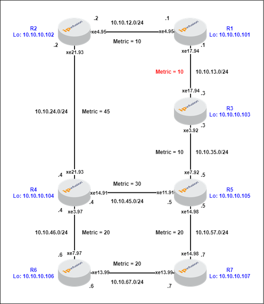
Figure-1: R1-R3 Metric = 10 (default)
In the above scenario (Figure-1), R2 computes the least cost path to reach the destination R6 through R4, resulting in the route R2 -> R4 -> R6 with a total metric of 45 + 20 = 65.
LFA is used to protect the link between R2 and R4.
R2 identifies least cost to repair node R1.
Point of local repair (PLR is node upstream of protected link)
Repair node is node to which packet is re-directed, when primary is not available.
LFA repair node requirement:
Repair node must be directly connected to PLR.
Repair node must satisfy loop free criterion i.e. in pre-convergence state, its least cost path to destination R6 must not traverse the PLR i.e. R2.
For Link Protection: Repair node total cost to destination must be less than the sum of repair node cost to PLR and PLR total cost to destination.
For Node Protection: Repair node total cost to destination must be less than the sum of repair node cost to primary next-hop and primary next-hop total cost to destination.
LFA after R2->R4 link break:
R2 primary route to R6 is not available.
R2 sends traffic to R6 via the repair node i.e. R2->R1.
LFA Limitation
LFA does not provide coverage for all destination in all topology. (Topology dependent)
If we increase the cost between R1->R3 to 30, R1 (repair node) does not satisfy loop free criterion, as its least cost to destination (R6) is via link R2->R4.

Figure-2: R1-R3 Metric = 30
Repair node (R1) to destination (R6) cost calculations:
R1-> R2->R4->R6 = 75
R1-> R3->R5->R7->R6 = 80
R1->R3->R5->R4->R6 = 90
Hence, LFA cannot protect traffic flowing from R2->R6, if R2->R4 link fails.
Remote LFA (RLFA)
RLFA serves the limitation of LFA by allowing some node to be as repair node, although they are not directly connected to PLR.
A repair tunnel is the least cost path from the PLR to the repair node.
RLFA supports link and node protection.
For example, in above scenario (Figure-2) where LFA cannot protect against a failure on the R2 to R4 link, RLFA can be employed.
R2 calculates least cost to R6 via R4 as Primary.
R2->R4->R6 = 65
R2->R1->R3->R5->R4->R6 = 100
R2->R1->R3->R5->R7->R6 = 90
R2 identifies a repair node (R3), not directly connected.
R2 creates a repair tunnel to repair node
R2 installs a backup path to R6 via repair tunnel.
This process allows R2 to route traffic to R6 via an alternative path through the repair node (R3), which can be crucial in scenarios where direct connections to the repair node are not feasible.
To understand how the calculation of a repair node works when it is not directly connected to the Point of Local Repair (PLR), let us go through the following:
P Space
This defined the set of other routers that can reach without traversing over failed link over pre-converged shortest path.
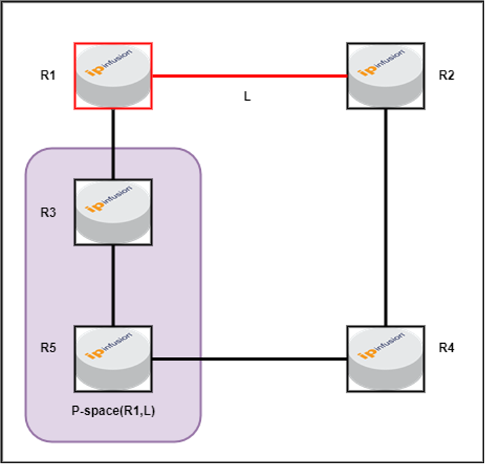
Figure-3: P-space for R1(PLR) for link L
In this scenario, the default link metric between routers is 10. Both R3 and R5 can reach R1 (PLR) via the least-cost path without traversing the link L (which is the link we are attempting to protect). Therefore, R3 and R5 are identified as P-space routers, unlike R4, since R4’s least-cost path to R1 involves using link L.
Extended P Space
The extended P-space of the protecting router with respect to the protected link is the union of the P-spaces of the neighbours in that set of neighbours with respect to the protected link.
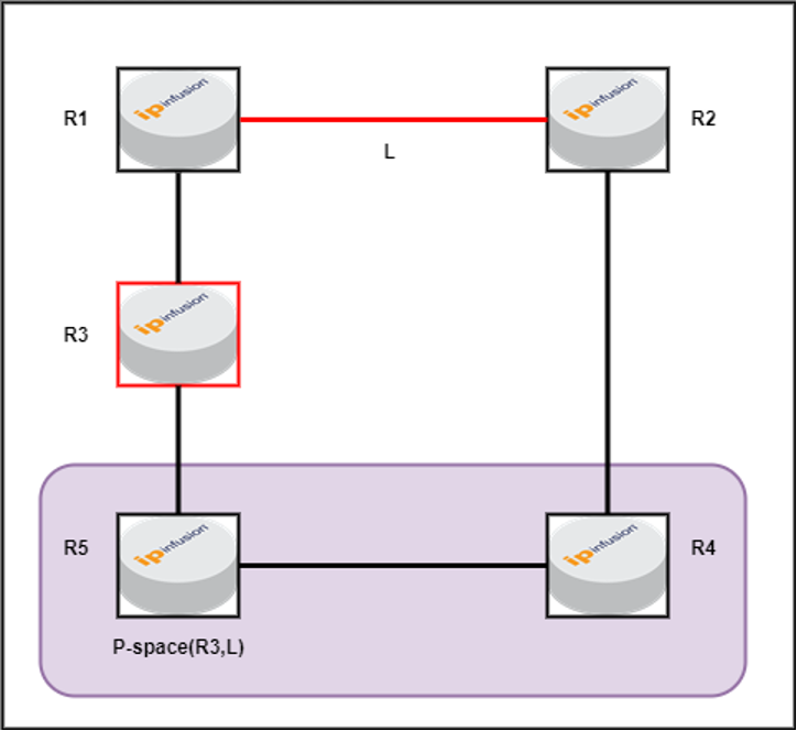
Figure-4: Extended P-space i.e. P-space for R3(PLR) for link L
In this scenario, both R4 and R5 can reach R3 via the least-cost path without traversing the link L (which is the link we are attempting to protect). Therefore, R4 and R5 are identified as extended P-space routers.
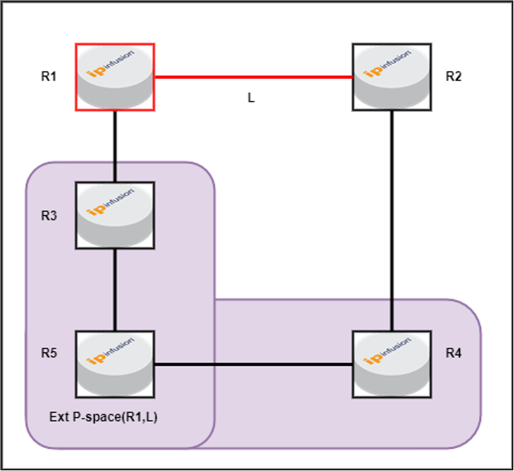
Figure-5: Union of Extended P-space and P-space for R1(PLR) for link L
The union of P-space and extended P-space comprises all P-space routers. In this case, R3, R4, and R5 are identified as the complete set of P-space routers.
Q-Space
Q-space of a router with respect to a protected link is the set of routers from which that specific router that can be reached without any path transiting that protected link.
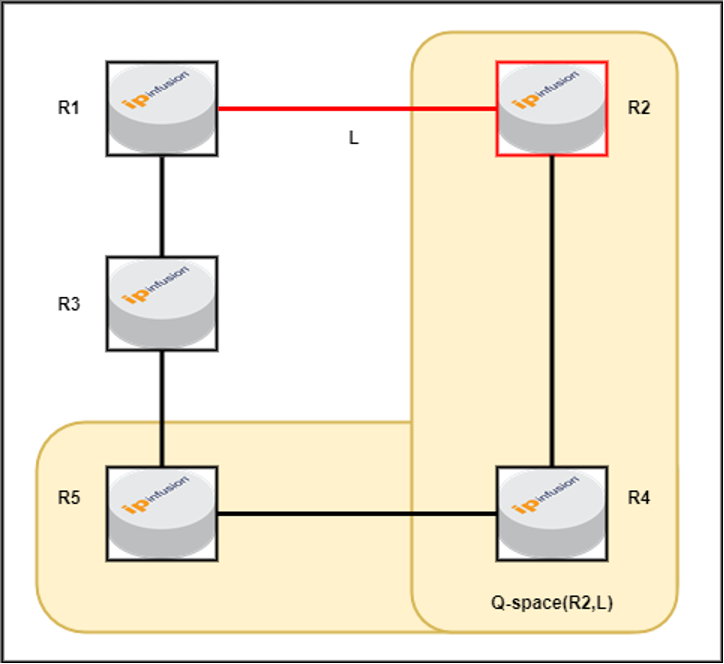
Figure-6: Q-space for R2(destination) for link L
In this scenario, both R4 and R5 can reach R2 via the least-cost path without traversing the link L (which is the link we are attempting to protect). Therefore, R4 and R5 are identified as Q-space routers, unlike R3, since R3’s least-cost path to R2 involves using link L. And destination (R2) is also considered in Q-space router.
PQ-Node
The node intersecting the P-Space & Q-Space is PQ node. If we have more than one PQ node, then the node closest to PLR is chosen, here R5 is chosen as PQ node.
RLFA link protection repair node requirement:
Repair node must reside in PQ space.
In Figure-2, the PLR (R2) P space contains nodes that it can reach, without traversing the protected link i.e. R2->R4.
R1, R3, R5 and R7 is P space.
The destination (R6) Q space contains nodes that it can reach, without traversing the protected link i.e. R2->R4.
R3, R4, R5, R6 and R7 is Q space.
PQ space is intersection of P space and Q space, here R3, R5 and R7.
R3 is chosen as repair node, as it is closest to PLR (R2).
RLFA link protection after break:
R2->R4 link breaks.
R2 primary path to R6 becomes unreachable via R4.
R2 sends traffic to R6 via repair node R3 i.e. through repair tunnel.
Connectivity between R2 and R6 is preserved during convergence.
RLFA node protection before break:
RLFA protects node R4 failure.
R2 primary path to R6 via R4.
R2 identifies R3 as repair node.
R2 creates repair tunnel to repair node.
R2 installs a backup route to R6 via repair tunnel.
RLFA node protection repair node requirements:
The repair node must be in PQ space.
In Figure-2, the PLR P space contains nodes that it can reach, without traversing the protected node i.e. R4.
R1, R3, R5 and R7 is P space.
The destination (R6) Q space contains nodes that it can reach, without traversing the protected node i.e. R4.
R3, R5 and R7 is Q space.
PQ space is intersection of P space and Q space.
R3 is chosen as repair node, as it is closest to PLR.
RLFA Limitations:
RLFA does not provide coverage for all destination in all topology. (Topology dependent)
Here, we increase the cost between R1->R3 to 100.

Figure-7: R1-R3 Metric = 100
R2’s P space has only R1.
R6’s Q space has R3, R4, R5, R6, and R7.
PQ space is empty.
Hence, RLFA cannot protect traffic flowing from R2->R6, if R2->R4 link fails.
Topology Independent LFA (TI-LFA):
TI-LFA addresses RLFA limitations by using SR policy as repair tunnel.
Repair node can be outside of P space.
However, repair node must be within Q space.
Supports link and node protection.
TI-LFA link protection before break:
In Figure-7, TI-LFA protects R2-R4 link.
R2 primary path to R6 is via R4.
R2 identifies repair node as R3.
R2 creates an SR repair tunnel to repair node.
R2 installs a backup route to R6 via repair tunnel.
TI-LFA link protection repair node requirements:
Repair node must be in Q space.
P space contains nodes that can reach the PLR (R2), without traversing the protected link (R2->R4).
Here, R1 is in P space.
Q space contains nodes that can be reach the destination (R6), without traversing the protected link (R2->R4).
Here, R3, R4, R5, R6, R7 is in Q space.
R3 is chosen as the repair node, as it is closest to the PLR.
TI-LFA link protection after break:
R2-R4 link breaks.
R2 primary path to R6 via R4 becomes unreachable.
R2 sends traffic to destination R6 via backup route.
R2 push node/prefix sid of P router i.e. R1 as first segment and have adjacency sid for the link R1-R3 as second segment on the repair tunnel.
R3 forward the packet to R6 through its least cost path.
Connectivity between R2 and R6 is preserved during convergence.
OcNOS Steps for TI-LFA Calculation:
Each node, where TI-LFA is enabled,
- Calculate post convergence SPT for each outgoing link.
- Calculate P and Q Space for each node.
- Find PQ node(s), if there is (are) an overlapping node between P and Q space. Intersect PQ nodes with Post convergence path and pick the PQ node closest to Source.
- If no PQ node found, find P and Q nodes, which are directly connected and intersect with post convergence paths.
- After calculation of P and Q nodes, install repair tunnel based on common or disjoint P and Q node.
- IGP calculates Backup FTN and backup ILM for each primary FTN and ILM using one of the repair tunnels and send to NSM.
TI-LFA Configuration for ISIS-SR:

Note: Fast-reroute TI-LFA command need to be enabled for the respective levels.
Case-1 Validation: When R1-R3 metric is 10 as shown in Figure-1
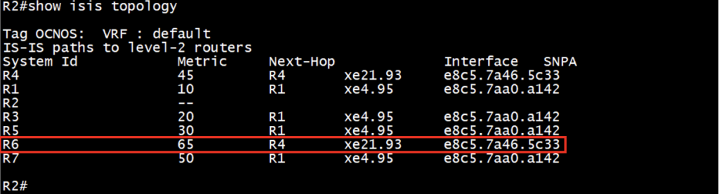
R2 least cost to R6 via R4.
Hence, for destination R6, we need to protect link R2-R4 failure and find loop free alternate path to destination R6.
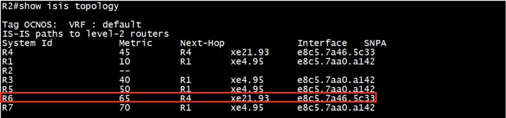
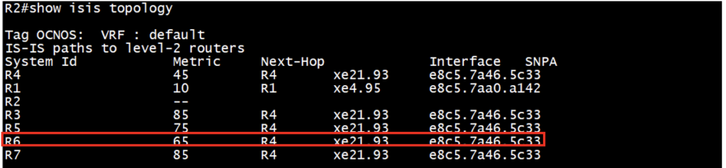
Check the ISIS topology details:
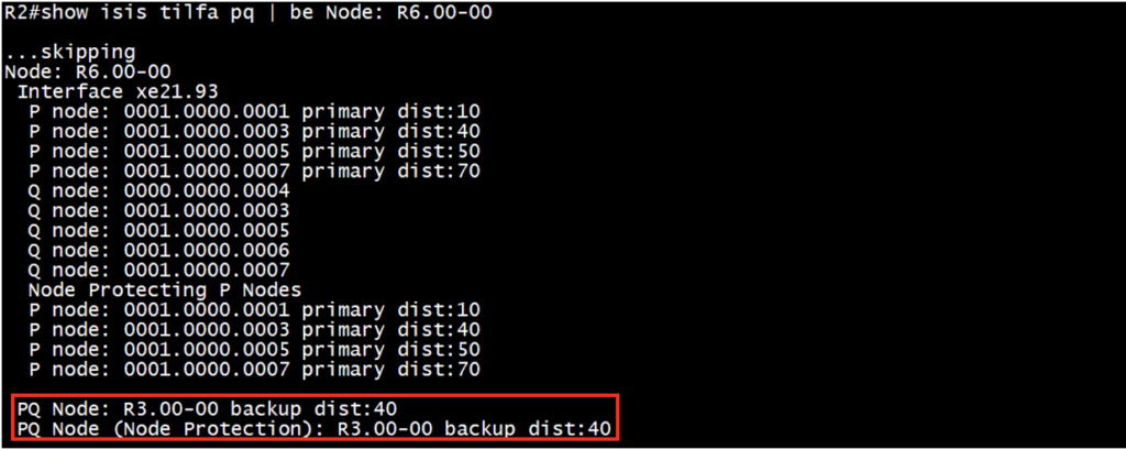
Check the P space nodes, Q space node and PQ node (if we have common PQ):
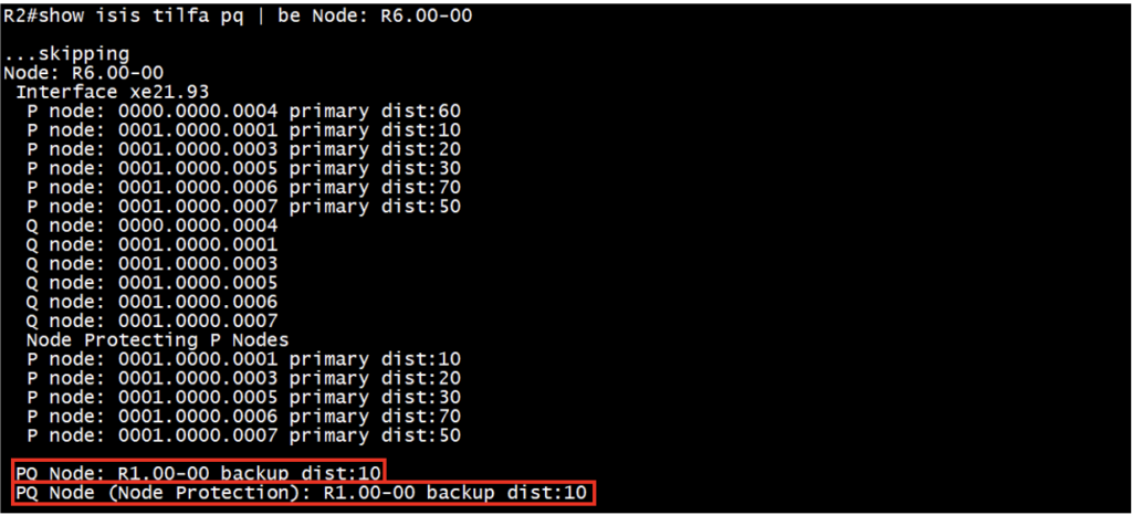
For link protection:
P-space nodes: R4, R1, R3, R5, R6, R7
Q-space nodes: R4, R1, R3, R5, R6, R7
Common PQ node: R1
For node protection:
P-space nodes: R1, R3, R5, R6, R7
Q-space nodes: R1, R3, R5, R6, R7
Common PQ node: R1
Check the ISIS-SR primary route and TI-LFA backup route along with backup tunnel:
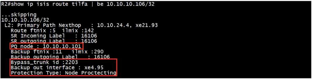
This tell on the primary and backup path outgoing label, outgoing interface, PQ node and the protection type, here node protection means it has node as well as link protection. Also it tells about the backup/repair tunnel with the field Bypass trunk id and it’s detail is shown in next command.
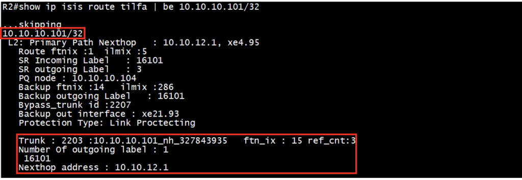
For bypass trunk id 2203, details can be verified under the PQ node FTN (R1 is PQ node as shown in previous command). This repair tunnel (Bypass trunk) is automatically created and it has number of outgoing label with label stack and nexthop ip address.
Case-2 Validation: When R1-R3 metric is 30 as shown in Figure-2
R2 least cost to R6 via R4.
Hence, for destination R6, we need to protect link R2-R4 failure and find loop free alternate path to destination R6.
Check the ISIS topology details:
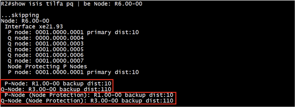
Check the P space nodes, Q space node and PQ node (if we have common PQ):
For link protection:
P-space nodes: R1, R3, R5, R7
Q-space nodes: R4, R3, R5, R6, R7
Common PQ node: R3
For node protection:
P-space nodes: R1, R3, R5, R7
Q-space nodes: R3, R5, R6, R7
Common PQ node: R3
Check the ISIS-SR primary route and TI-LFA backup route along with backup tunnel:
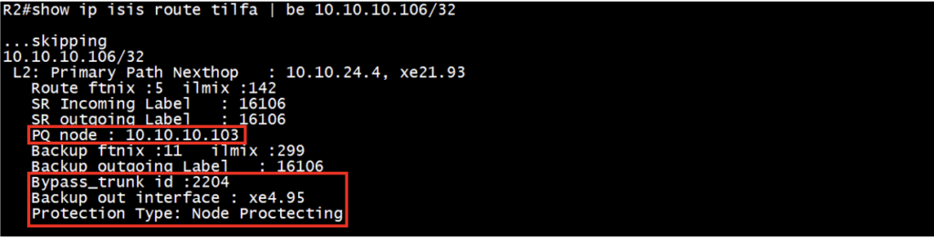
Verify the primary and backup path outgoing label, outgoing interface, PQ node, Bypass trunk id and the protection type.
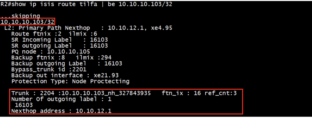
For bypass trunk id 2204, details can be verified under the PQ node FTN (R3 is PQ node). This repair tunnel (Bypass trunk) has number of outgoing label with label stack and nexthop ip address.
Case-3 Validation: When R1-R3 metric is 100 as shown in Figure-7
R2 least cost to R6 via R4.
Hence, for destination R6, we need to protect link R2-R4 failure and find loop free alternate path to destination R6.
Check the ISIS topology details:
Check the P space nodes, Q space node and PQ node (if we have common PQ):
For link protection:
P-space nodes: R1
Q-space nodes: R4, R3, R5, R6, R7
Disjoint PQ node: P-space nodes: R1, adjacent Q-space node: R3
For node protection:
P-space nodes: R1
Q-space nodes: R3, R5, R6, R7
Disjoint PQ node: P-space nodes: R1, adjacent Q-space node: R3
Check the ISIS-SR primary route and TI-LFA backup route along with backup tunnel:
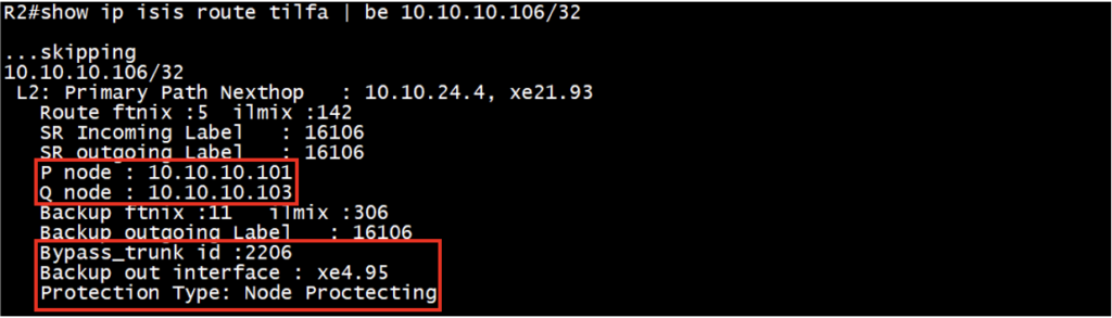
Verify the primary and backup path outgoing label, outgoing interface, P node, Q node, Bypass trunk id and the protection type.
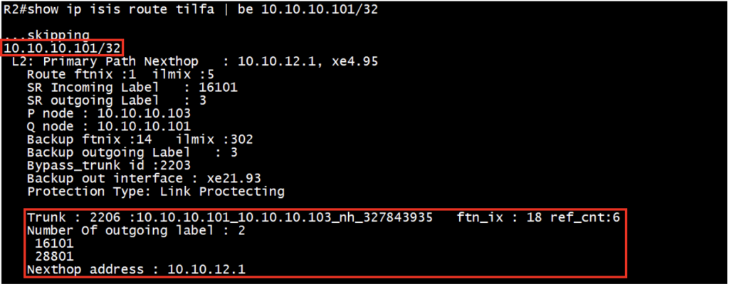
For bypass trunk id 2206, details can be verified under the P node FTN (R1 is P node). This repair tunnel (Bypass trunk) has number of outgoing label with label stack and nexthop ip address.
Check the MPLS forwarding-table (FTN) entries in software (NSM):
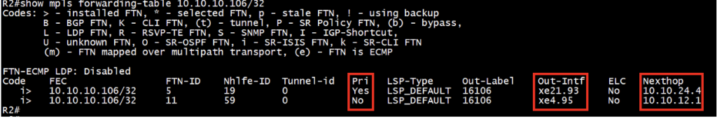
Ensure both primary and backup Forwarding-table (FTN) entries installed for the destination loopback addresses. It is essential to perform this check on the source router.
Check the MPLS ilm-table entries in software (NSM):
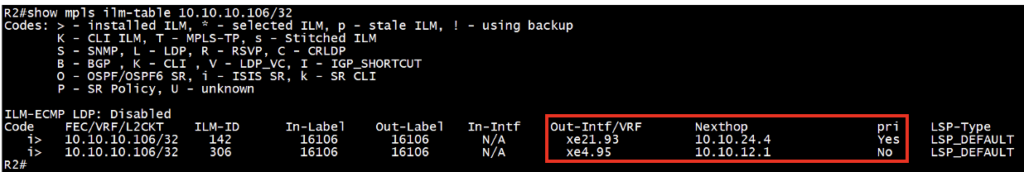
Ensure both primary and backup MPLS ILM-table (Incoming Label Mapping Table) entries installed for the destination loopback addresses. It is essential to perform this check on the transit router.
Advanced Troubleshooting (Hardware Level): If issues persist:
Check the MPLS FTN entries in hardware (HSL):

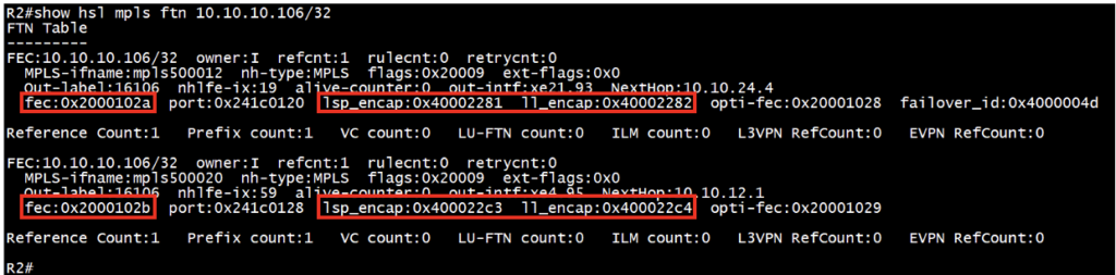
Records “fec”, “lsp_encap”, and “ll_encap” for respective FTN on source router for both primary and backup entries.
Check the MPLS ILM entries in hardware (HSL):
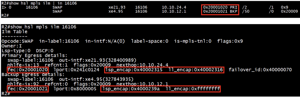
Records “fec”, “lsp_encap”, and “ll_encap” for respective ILM on transit router for both primary and backup entries.
Check the MPLS FEC entries for respective FTN entries from above HSL output:

Ensures the presence of “fec” entries collected from previous step for FTN.
Check the MPLS FEC entries for respective ILM entries from above HSL output:

Ensures the presence of “fec” entries collected from previous step for ILM.
Check the encap-db entries for respective FTN entries from above HSL output:
Ensures the presence of “lsp_encap” and “ll_encap” entries collected from previous step for FTN.
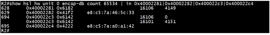
Check the encap-db entries for respective ILM entries from above HSL output:
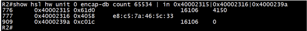
Ensures the presence of “lsp_encap” and “ll_encap” entries collected from previous step for ILM.
“lsp_encap” is to check the label mapping in hardware and “ll_encap” is ethernet/mac i.e. next-hop interface mac.
Conclusion:
Incorporating Topology-Independent Loop-Free Alternate (TI-LFA) enhances network resilience by providing agile and effective Fast Reroute (FRR) capabilities. This strategic combination empowers networks to swiftly recover from link or node failures, ensuring uninterrupted service delivery and operational continuity. With TI-LFA on OcNOS, network operators can confidently navigate dynamic environments while optimizing and maintaining exceptional performance.
Explore the seamless integration of TI-LFA with OcNOS to fortify your network against disruptions and elevate overall network reliability.
Next Topic: LDP to SR Migration in OcNOS
Read our previous blogs on this topic:
Segment Routing (SR): Understanding the WHY, WHAT, and HOW
Segment Routing Extension with IGP (IS-IS) in OcNOS
Contact us today to learn how OcNOS can offer Segment Routing for your network.

Suraj Kumar Singh is Senior Solution Lead at IP Infusion.