We all know that Equal-cost-Multipath (ECMP) helps in better utilization of the network and increases network redundancy. In this article we will discuss overlay ECMP using Ethernet VPN (EVPN) with Virtual Extended LAN (VxLAN) encapsulation. In the beginning we will try to understand what overlay ECMP is, then we will extend this to further use cases.
Consider the below popular Data Center (DC) Clos topology for the discussion.
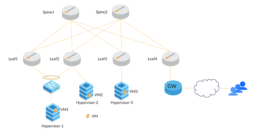
Figure 1: Topology
In the above diagram we have hosted Virtual Machines (VMs) serving web services on different hypervisors (Top of Rack (TOR) switch, multiple border leafs for redundancy, Firewall (FW) and Gateway (GW) connecting to multiple border leafs and GW/FW redundancies have been omitted to keep it simple).
If users want to reach VM3 then traffic has to travel via a single tunnel from Leaf4 to Leaf3. To reach Leaf3, tunnelled-traffic will go via both the spine nodes; this load sharing is generic L3 IP ECMP, and in underlay-overlay context it is known as underlay ECMP.
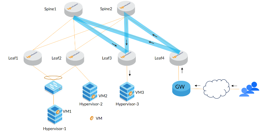
Figure 2: Underlay ECMP
Here tunnelled packet source and destination IP addresses remain the same; the packets differ and load balancing happens because of random source ports that are generated for each stream by the Leaf4 device.
If users wants to reach VM1, traffic can travel from Leaf4 to Leaf1 or Leaf4 to Leaf2. This load balancing happens because of EVPN-Multihoming having the same Ethernet Segment Identifier (ESI) configured on both leafs towards the switch. This is ESI based overlay load balancing (LB). In this case two tunnels are put together to form the Link Aggregation (LAG) group at Leaf4; traffic towards VM1 selects the tunnel based on hashing and both of the tunnels’ traffic goes via both of the spines. We call this overlay LAG because traffic is getting into multiple tunnels/links to reach a single ESI/access segment.
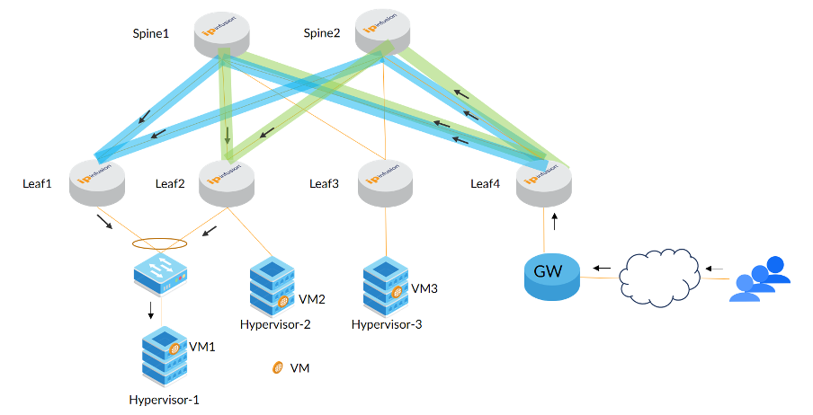
Figure 3: ESI based L2 Load balancing
Now let us get into L3 based load balancing, which is ECMP. Consider VM2 and VM3 are hosting the same IP-X. At Leaf4 this IP-X will show up as an ECMP route pointing both of the L3 tunnels to Leaf3 and Leaf2.
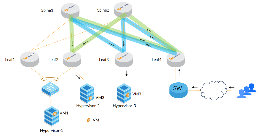
Figure 4: Overlay ECMP Load balancing
In the above, traffic is handled by both VMs; the consistent hashing will ensure a given session packet will always land on the same destination VM.
Here Leaf2 and Leaf3 would have announced the same IP-X/32 prefix to Leaf4 in overlay, i.e. EVPN Type-5 prefix-route. In Leaf4 when the same prefixes are received in a given VPN, it forms the ECMP path consisting of two tunnels. The traffic towards IP-X will take this ECMP path.
When we host VMs (which are hosting IP-X) in all the hypervisors of the given topology; we can see that the complete fabric will be carrying the traffic.
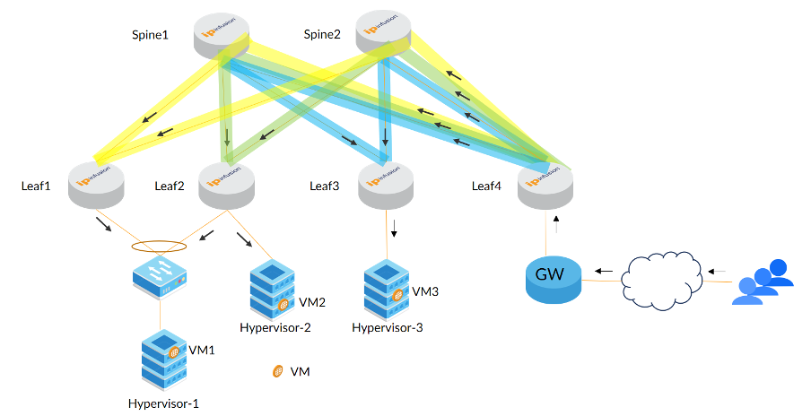
Figure 5: Complete fabric usage
In the next blog we will increase the number of VMs hosting the same IP, talk about the complexities involved and share how to solve them.
Contact us today to learn more about IP Infusion OcNOS-based networking software.

Prasanna Kumara S is a Technical Marketing Engineer for IP Infusion.