Part 1 of a multi-part series on Segment Routing Traffic Engineering with OcNOS.
Challenges with RSVP-TE and LDP at Scale
If you have built RSVP-TE tunnels, you know what they cost: per-tunnel state on every transit node, a re-signaling storm every time a link flaps, and an operational model that breaks at scale. If you have run LDP in parallel with your IGP, you have distributed labels for prefixes the IGP already knows, through a second control plane that needs IGP-LDP synchronization and its own timer and BFD management, and that still cannot do traffic engineering.
Segment Routing removes both problems. There is no per-hop state and no parallel signaling protocol, only an ordered list of forwarding instructions. The ingress node encodes that list in the packet header, and every router in the path executes it without keeping any knowledge of the traffic flow.
This is Part 1 of a hands-on SR-TE series. By the end of this post, you will understand how SIDs and the SRGB work, how SR Policies define explicit and dynamic forwarding paths, and how to verify the full forwarding chain, from IS-IS SID advertisement to hardware MPLS table programming on a real OcNOS router.
LDP vs RSVP-TE vs SR-MPLS: At a Glance
| 項目 | LDP | RSVP-TE | SR-MPLS |
|---|---|---|---|
| Signaling protocol | LDP (parallel to the IGP) | RSVP-TE (per tunnel) | None, native to the IGP |
| Per-hop state | Yes (per prefix) | Yes (per tunnel) | いいえ |
| Scalability | Moderate | Limited (state explosion) | 高 |
| Explicit path control | いいえ | はい | Yes (SR Policy) |
| Fast reroute | LFA / rLFA | FRR (backup tunnels) | TI-LFA (topology independent) |
| Controller integration (if needed) | Limited | PCEP (complex) | PCEP and BGP-LS (native, optional) |
| Label distribution | LDP protocol | RSVP extensions | IS-IS / OSPF TLVs |
Note: Controller integration is optional. OcNOS supports PCEP for controller-driven path computation and BGP-LS for topology export to external controllers. SR-PCE integration is covered in Part 4 of this series.
How SR Works: Source Routing without Per-Hop State
Segment Routing uses a source-routing model. The ingress node, called the headend, determines the complete forwarding path and encodes it as an ordered list of segments in the packet header. Transit nodes execute these instructions without any per-flow or per-tunnel state.
Analogy: the label stack as a pre-printed itinerary. Think of the SR label stack as a pre-printed itinerary handed to a traveler at the airport. Every layover (transit node) is listed in order. No travel agent needs to be called mid-journey: each node reads the next destination and forwards accordingly. The carrier knows nothing about the end-to-end trip; it simply drops the traveler at the next stop on the list.
Segment Types
- Prefix SID: a globally unique identifier assigned to a router's loopback interface. It instructs the network to forward the packet to that node along the IGP shortest path.
- Adjacency SID: a locally significant label assigned to a specific link between two neighboring routers. It steers traffic over that exact link, overriding the IGP path.
Note: The examples in this post use Prefix SIDs only. Adjacency SIDs will be demonstrated in a later part of this series.
MPLS Data Plane Operations
Segment Routing reuses the existing MPLS data plane without modification, through three label operations:
- PUSH: the headend imposes one or more labels onto the packet, forming the segment list (label stack).
- SWAP: a transit router replaces the top label with the outgoing label for the same segment and forwards the packet. With a common SRGB, the outgoing label has the same value.
- POP: a router removes the top label, exposing the next segment or delivering the original packet. When the penultimate router does this, it is called Penultimate Hop Popping (PHP): the destination router receives the inner payload directly, which saves one label lookup. PHP is the default behavior. The
no-phpflag disables it when the tail-end router needs to receive the labeled packet, for example for service-layer processing.
IS-IS carries SID and SRGB advertisements in new sub-TLVs. The Router Capability TLV 242 advertises the SRGB range, Prefix-SID sub-TLVs inside TLV 135 (Extended IP Reachability) distribute Prefix SID indices to every router in the domain, and Adjacency SID sub-TLVs inside TLV 22 (Extended IS Reachability) advertise locally significant labels for individual links. Because SID indices are flooded in IS-IS, every router builds a complete SID-to-label map without any additional protocol adjacency, so no separate label distribution protocol (LDP or RSVP-TE) is required.
SRGB and SID Calculation
The Segment Routing Global Block (SRGB) is a range of MPLS labels reserved for SR within the domain. All routers in the SR domain use a common SRGB so that every label is interpreted the same way everywhere.
Analogy: the SRGB as a shared phone book prefix. Every router in the domain agrees that numbers in the range 16000 to 23999 belong to SR. A router's SID index is its extension number. Dialing the prefix plus the extension (16000 + 7 = 16007) reaches that router uniquely, and every other router can compute the same number without asking anyone.
SRGB Label Range
- Default SRGB: 16,000 to 23,999 (8,000 globally significant labels)
- SRLB (Segment Routing Local Block): 14,080 to 15,999 (1,920 locally significant labels)
- Labels from 24,000 up: dynamically allocated local labels, such as Binding SIDs
All nodes should use a common SRGB; this is strongly recommended and standard practice. Different SRGBs per node are permitted, but they add operational and troubleshooting complexity. A custom SRGB range can be configured, and it should then be uniform across the SR domain.
SID-to-Label Calculation
Each router advertises its Prefix SID as a domain-wide unique, zero-based index, not as a raw MPLS label. The label used in the data plane is derived as follows:
Label = SRGB Base + Prefix-SID Index

SRGB Base         = 16000
Prefix-SID Index  = 1
Resulting Label = 16000 + 1 = 16001 (R1's Prefix SID label)Any router in the domain can therefore compute the forwarding label for any other router from the SRGB base and the advertised SID index, with no label distribution protocol.
Reference Topology
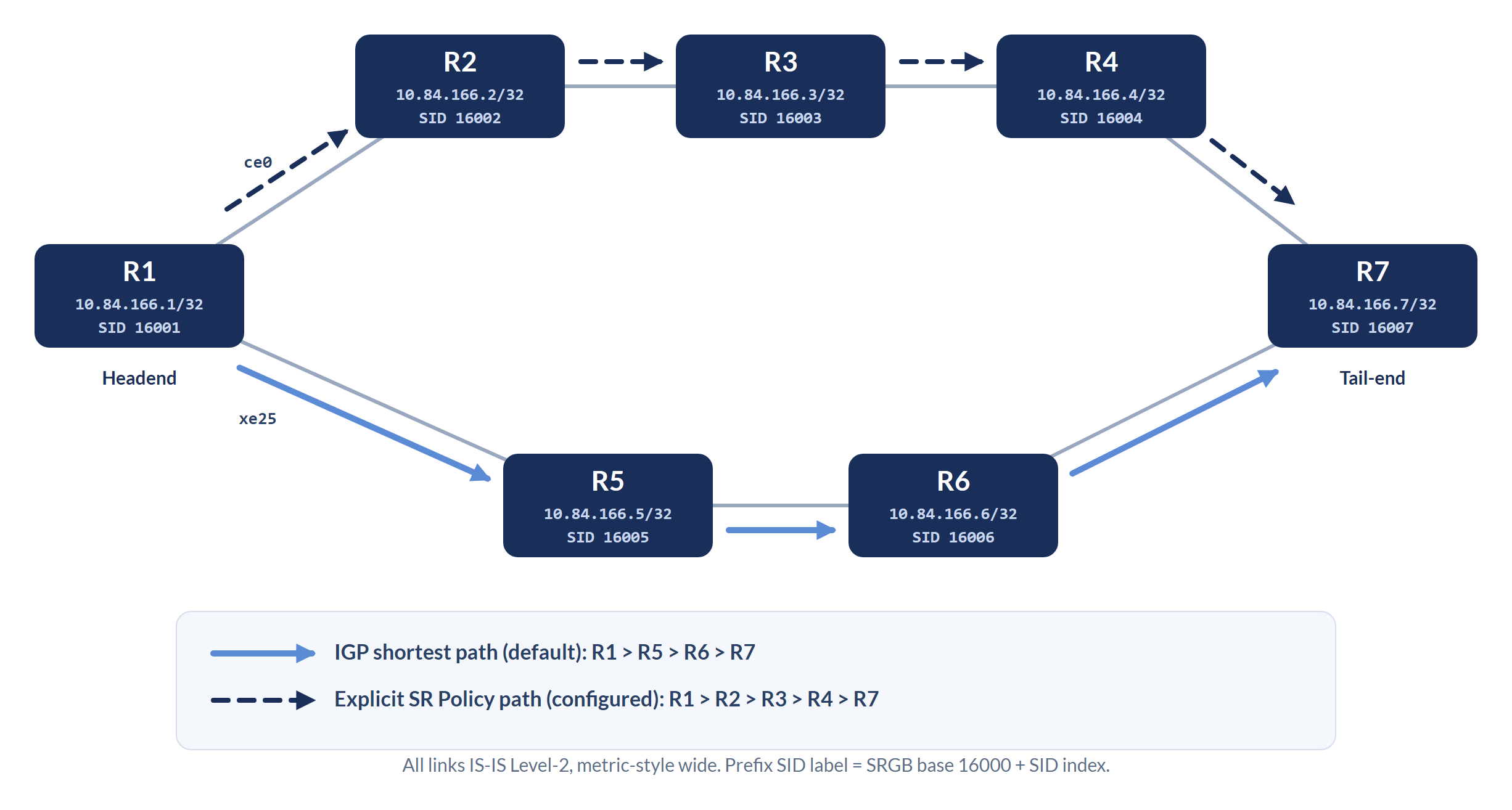
The configuration below sets the no-php flag on R1's loopback prefix SID. It disables Penultimate Hop Popping for that SID, so the penultimate router forwards the label intact instead of popping it. Use it when the tail-end router needs to receive the labeled packet, for example when the label carries service-layer information. In most intra-domain SR deployments, PHP is preferred and no-php is omitted.
SR Policies: Defining Traffic Paths Beyond the IGP
An SR Policy steers traffic through the network along a pre-determined path that meets specific steering requirements. Instead of relying on the IGP to select the best path, the policy explicitly defines the sequence of segments the traffic must traverse.
Each SR Policy is uniquely identified at the headend by a three-element tuple, (Head-end, Color, End-point):
- Head-end: the router that originates the SR Policy
- Color: a numerical identifier that differentiates policies
- End-point: the destination prefix or node
Color acts as a policy-based forwarding identifier. When several SR Policies exist between the same headend and endpoint, Color tells them apart and lets specific traffic flows be associated with the right policy through route coloring.
Binding SID (BSID)
Each SR Policy is also assigned a Binding SID (BSID), a locally allocated MPLS label that acts as a single-label handle for the entire policy. When traffic arrives at the headend with the BSID as its top label, the router steers it along the segment list of the active candidate path.
The BSID serves two purposes: it simplifies service integration, and it enables hierarchical SR, where one SR Policy references another through its BSID to build nested forwarding constructs. You will see the BSID (label 24960 in our examples) in the verification output. Part 3 of this series shows how the BSID links SR Policies together.
Explicit vs Dynamic Paths: Determinism vs Adaptability
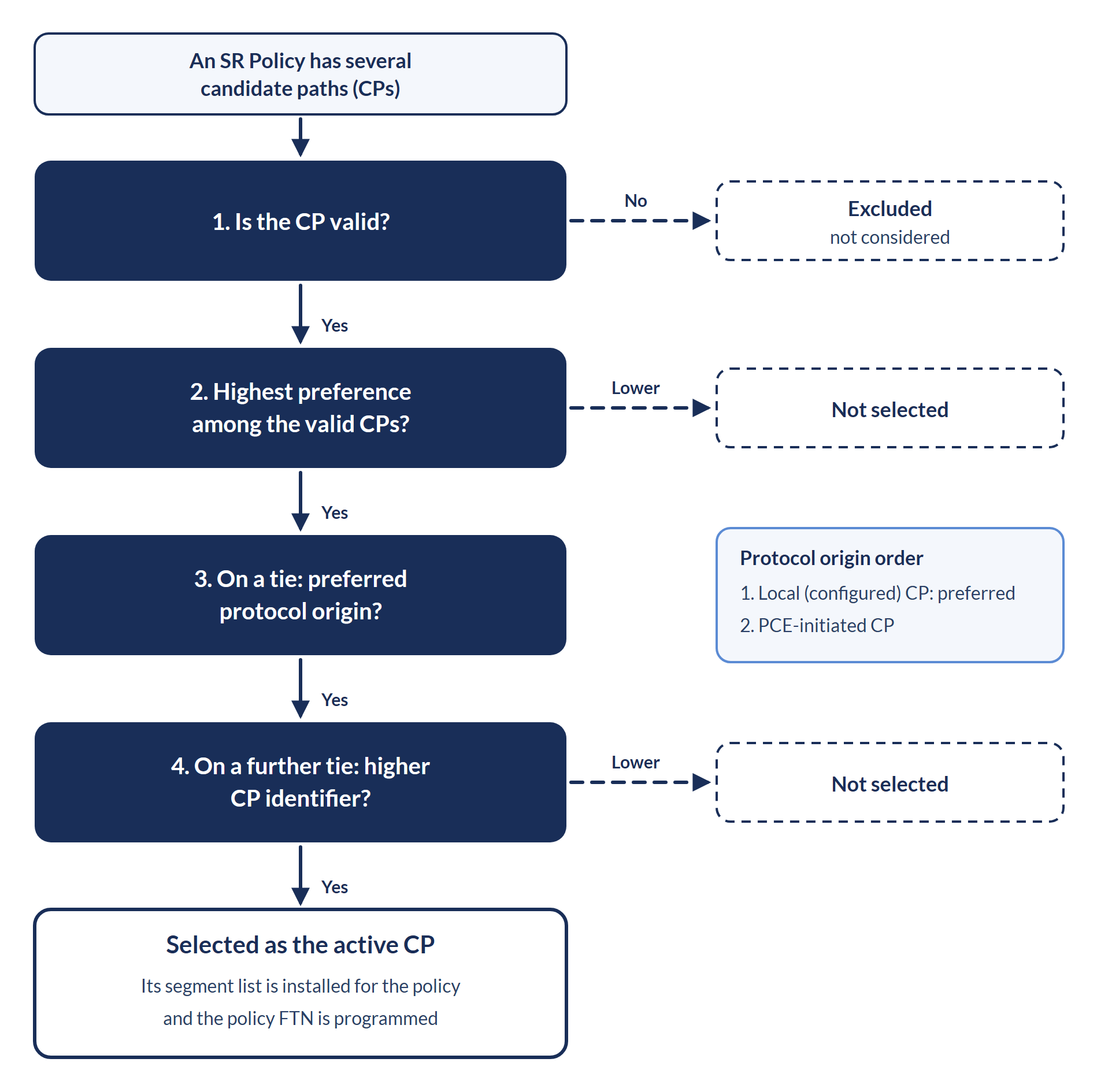
An SR Policy consists of one or more candidate paths (CPs). Each candidate path is identified by the tuple of protocol origin, originator, and discriminator. Only the valid candidate path with the highest preference is installed as the active forwarding path.
Explicit Candidate Path
An explicit candidate path is defined by a segment list, an ordered sequence of SIDs that dictates the forwarding path. The segment list can be configured on the device or received from a controller. Either way the path is fully deterministic, with each hop specified, so the operator or controller can enforce exact traffic steering independent of IGP metrics.
For an explicit segment list, the headend resolves the next hop of the first SID only when it installs the policy. It does not validate the later SIDs in the list, because forwarding relies on hop-by-hop processing of the imposed SID stack.
Note: If an explicit segment list includes Adjacency SIDs, configure them as persistent (static) Adjacency SIDs. Dynamic Adjacency SIDs are allocated locally at startup and can change after a router restart, which would invalidate the segment list.
Analogy: explicit is a hard-coded GPS route. You have locked in the turns in advance. The network follows your instructions exactly, regardless of traffic or conditions. This gives maximum determinism, but the route needs a manual update if the topology changes.
Dynamic Candidate Path
A dynamic candidate path expresses an optimization objective through a set of constraints instead of a fixed segment list. The headend hands path computation to a local CSPF (Constrained Shortest Path First) engine in the IGP process. CSPF evaluates the topology against the constraints, which can include strict or loose intermediate nodes, and computes the segment list.
Analogy: dynamic is adaptive real-time navigation. CSPF reroutes traffic around network changes within the constraints you set. Unlike a hard-coded route, the computed segment list updates on its own when the topology changes.
If the topology changes and the computed path no longer satisfies the constraints, CSPF computes a new segment list and updates the forwarding state without operator intervention.
Trade-off: Explicit paths give maximum control and predictability but need manual updates when the topology changes. Dynamic paths adapt automatically, but CSPF needs accurate topology information (the TE extensions in IS-IS), and it may select a different path after each topology event.
Active Path Selection
When an SR Policy has several candidate paths, the router checks each path's validity and selects the valid path with the highest preference as the active path. If the active path becomes invalid, because a segment is unreachable or a constraint is violated, the valid path with the next highest preference is promoted automatically.
Tracing the Label Stack: How SR Policies Forward Traffic
Scenario 1: Default IGP Shortest Path
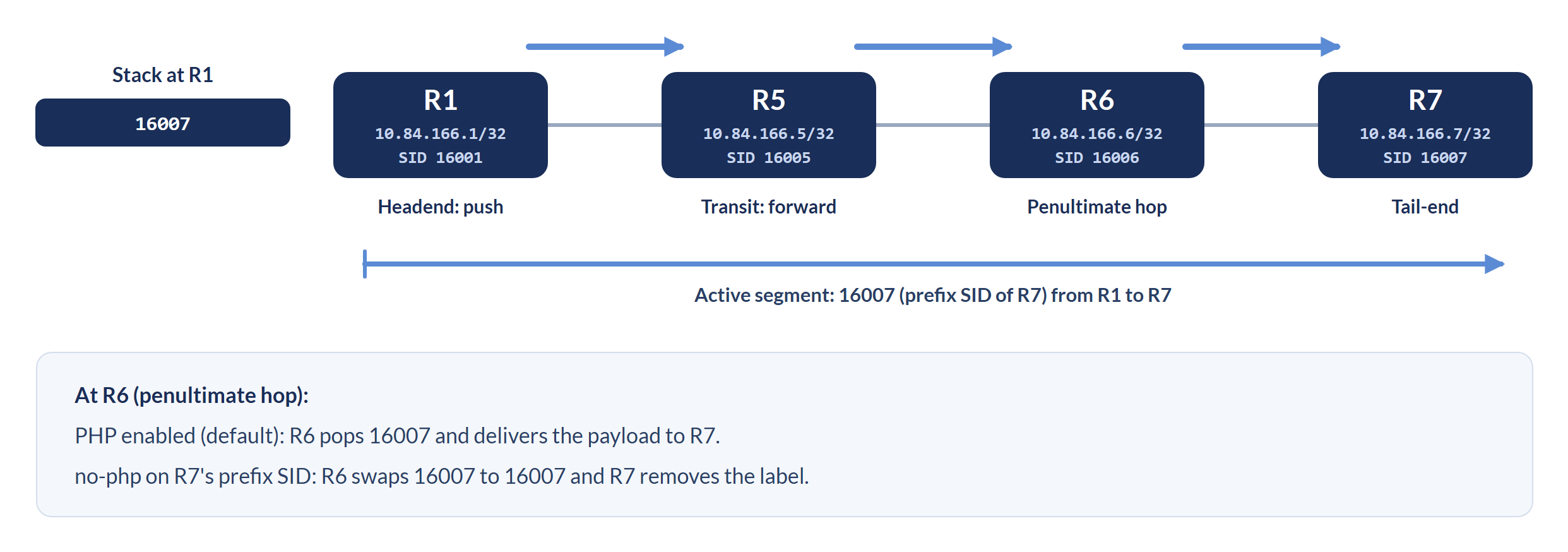
When traffic toward R7 carries only R7's Prefix SID (16007), the headend pushes the single label 16007 and the packet follows the IGP shortest path, R1 to R5 to R6 to R7. Each transit node forwards on the label using its MPLS forwarding tables (FTN and ILM). What R6 does depends on how R7 advertises its SID:
- PHP enabled: R6, the penultimate hop, pops 16007. This exposes the IP packet, or the next label in the stack, which R6 then delivers to R7.
- PHP disabled: R6 performs a SWAP instead. It replaces the incoming label with the outgoing label for R7's SID (with a common SRGB, still 16007) and forwards the labeled packet to R7.
Scenario 2: Explicit SR Policy Path
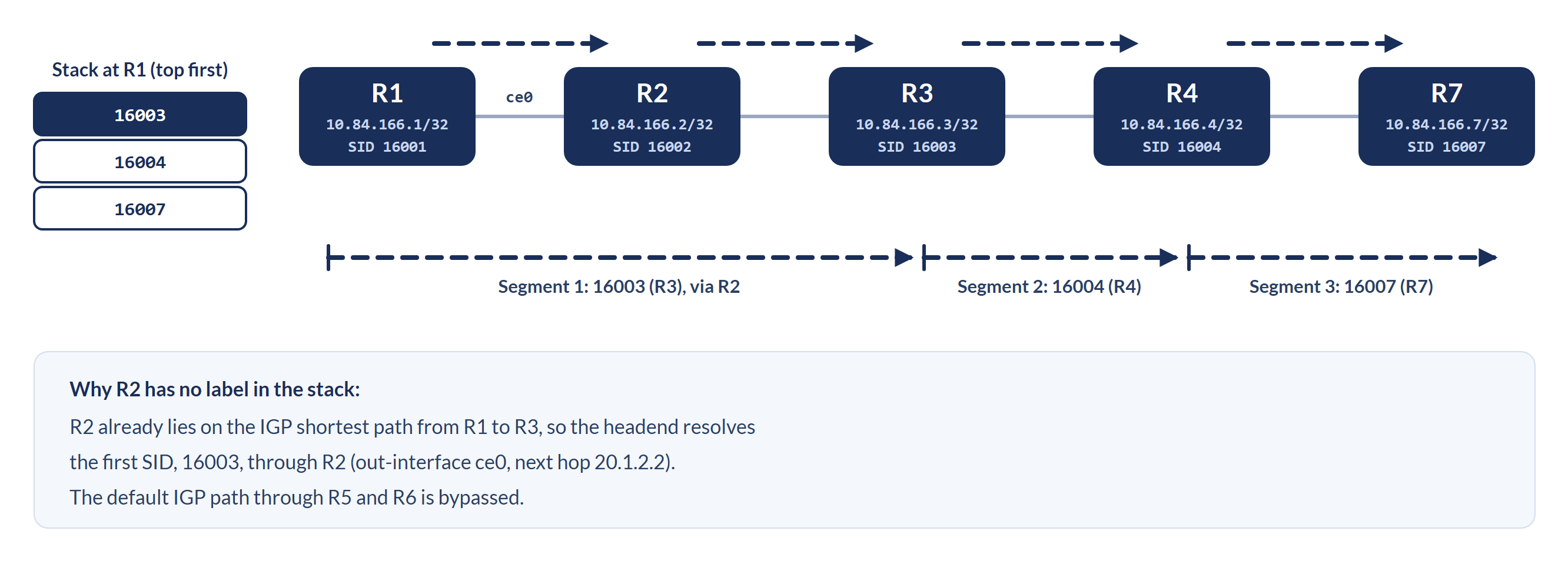
When strict path control is required, for example to force traffic toward R7 through R2, R3 and R4, the SR Policy programs a label stack on the headend. The segment list configured in this lab has three SIDs:
Label stack (top to bottom): [ 16003 | 16004 | 16007 ]

R1 -> pushes the stack; the IGP next hop toward R3 (16003) is R2, out ce0
R2 -> forwards on 16003 toward R3
R3 -> segment 16003 complete; forwards on 16004 toward R4
R4 -> segment 16004 complete; forwards on 16007 toward R7
R7 -> receives the traffic
R2 needs no SID of its own in the stack: it already lies on the IGP shortest path from R1 to R3, so the headend resolves the first SID, 16003, through R2. The traffic bypasses the default IGP shortest path through R5 and R6 and traverses the sequence of nodes set by the SR Policy.
Step-by-Step SR Configuration on OcNOS with IS-IS
The following configuration, taken from R1, shows SR with IS-IS and an SR Policy with both an explicit and a dynamic candidate path.
Step 1: Enable SR under IS-IS
router isis OcNOS
 is-type level-2-only
 metric-style wide
 mpls traffic-eng router-id 10.84.166.1
 mpls traffic-eng level-2
 capability cspf
 dynamic-hostname
 fast-reroute ti-lfa level-2 proto ipv4
 bfd all-interfaces
 net 49.0001.0000.0000.0001.00
 passive-interface loopback1
 segment-routing mpls
!
Note: TI-LFA (Topology-Independent LFA) provides fast reroute protection for SR paths. TI-LFA relies on Segment Routing and is covered in the tech blog ISIS-SR with TI-LFA in OcNOS.
Step 2: Assign a Prefix SID on the Loopback Interface
interface loopback1
 ip address 10.84.166.1/32
 prefix-sid index 1 no-php
!
The no-php flag disables Penultimate Hop Popping for this SID, so the penultimate router forwards the label intact to R1 instead of popping it. Use it when the receiving router needs to process the SR label itself.
Step 3: Configure an Explicit Segment List
Define a segment list with the explicit hop sequence, then bind it to an SR Policy identified by Color and End-point:
segment-routing
 traffic-engineering
  segment-list Explicit_Seglist_Policy_R1_to_R7
   index 10 segment-type-1 16003
   index 20 segment-type-1 16004
   index 30 segment-type-1 16007
  exit-sr-sl
  !
  policy ISIS_SR_Policy_R1_to_R7
   color 1 end-point 10.84.166.7
   candidate-path 2
    preference 120
    explicit segment-list Explicit_Seglist_Policy_R1_to_R7
   exit-pol-cp
   !
  exit-sr-pol
  !
 exit-te
Step 4: Add a Dynamic Candidate Path
For dynamic path computation, add a candidate path with constraints to the same policy. The local CSPF engine in IS-IS computes its segment list:
policy ISIS_SR_Policy_R1_to_R7
 color 1 end-point 10.84.166.7
 candidate-path 1
  dynamic-path isis
  constraints
   10.84.166.5 loose
  exit-cp-cons
  !
 exit-pol-cp
Candidate path 1 has no preference configured, so it takes the default of 100. It is computed by CSPF with a loose constraint through R5. Candidate path 2 (explicit, preference 120) takes precedence while both are valid, because the higher preference wins. If a segment of the explicit path becomes unreachable, the router falls back to the CSPF-computed path automatically.
Verifying SR End to End: From IS-IS Advertisements to Hardware
After configuring SR and the SR Policy, a structured verification sequence confirms that SID distribution, policy state, and hardware programming all work as intended. The output below was captured on R1.
Step 1: Verify SR Capability and SRGB Advertisement
R1#show isis segment-routing capability
Tag OcNOS  Segment-Routing:
-----------------------------------------------------
Advertisement Router Capability   :10.84.166.1
Algorithm0                        :0
SRMS Preference                   :0
Total SID'S Supported             :8000
SR ERLD                           :10
SID Range List Count              :1
SID's Range                       :16000 - 23999
Total SID's Supported (SRLB)      :1920
SRLB Range List Count             :1
SID's Range (SRLB)                :14080 - 15999
-----------------------------------------------------
Advertisement Router Capability   :10.84.166.2
Algorithm0                        :0
SRMS Preference                   :0
Total SID'S Supported             :8000
SR ERLD                           :10
SID Range List Count              :1
SID's Range                       :16000 - 23999
Total SID's Supported (SRLB)      :1920
SRLB Range List Count             :1
SID's Range (SRLB)                :14080 - 15999
-----------------------------------------------------
Advertisement Router Capability   :10.84.166.3
Algorithm0                        :0
SRMS Preference                   :0
Total SID'S Supported             :8000
SR ERLD                           :10
SID Range List Count              :1
SID's Range                       :16000 - 23999
Total SID's Supported (SRLB)      :1920
SRLB Range List Count             :1
SID's Range (SRLB)                :14080 - 15999
-----------------------------------------------------
Advertisement Router Capability   :10.84.166.4
Algorithm0                        :0
SRMS Preference                   :0
Total SID'S Supported             :8000
SR ERLD                           :6
SID Range List Count              :1
SID's Range                       :16000 - 23999
Total SID's Supported (SRLB)      :1920
SRLB Range List Count             :1
SID's Range (SRLB)                :14080 - 15999
-----------------------------------------------------
Advertisement Router Capability   :10.84.166.5
Algorithm0                        :0
SRMS Preference                   :0
Total SID'S Supported             :8000
SR ERLD                           :10
SID Range List Count              :1
SID's Range                       :16000 - 23999
Total SID's Supported (SRLB)      :1920
SRLB Range List Count             :1
SID's Range (SRLB)                :14080 - 15999
-----------------------------------------------------
Advertisement Router Capability   :10.84.166.6
Algorithm0                        :0
SRMS Preference                   :0
Total SID'S Supported             :8000
SR ERLD                           :6
SID Range List Count              :1
SID's Range                       :16000 - 23999
Total SID's Supported (SRLB)      :1920
SRLB Range List Count             :1
SID's Range (SRLB)                :14080 - 15999
-----------------------------------------------------
Advertisement Router Capability   :10.84.166.7
Algorithm0                        :0
SRMS Preference                   :0
Total SID'S Supported             :8000
SR ERLD                           :6
SID Range List Count              :1
SID's Range                       :16000 - 23999
Total SID's Supported (SRLB)      :1920
SRLB Range List Count             :1
SID's Range (SRLB)                :14080 - 15999
-----------------------------------------------------
R1#
R1#show isis segment-routing state
Tag OcNOS  Segment-Routing:
SR State:  SR_ENABLED
SRGB Start: 16000,  SRGB Range: 8000
Operational state:  enabled
R1#
Step 2: Verify the SID Mapping Table
R1#show isis segment-routing mapping-table ipv4 active
Tag OcNOS  Segment-Routing:
Conflict Resolution Policy: Quarantine
Prefix            SID Index    Range     Flags
10.84.166.1/32    1            1
10.84.166.2/32    2            1
10.84.166.3/32    3            1
10.84.166.4/32    4            1
10.84.166.5/32    5            1
10.84.166.6/32    6            1
10.84.166.7/32    7            1
Number of mapping entries in Active IPv4 Table: 7
Every router in the domain is visible, with SID indices 1 to 7 mapping to labels 16001 to 16007 (SRGB base 16000 plus the index).
Step 3: Verify the SR Policy Operational State
R1#show segment-routing policy
Policy-Name                        Color   End-point      State   Forwarding-Info
ISIS_SR_Policy_R1_to_R7            1       10.84.166.7    UP      16003/16004/16007/ce0
R1#
R1#show segment-routing policy detail
Policy-Name: ISIS_SR_Policy_R1_to_R7    Color 1      End-point 10.84.166.7      Tunnel-ID: 1
  Admin-Status: UP    Oper-Status: UP for 00:26:55
  State Transition Count: 1
  CSPF Retry Limit: 100    CSPF Retry Interval: 10
  Binding SID :
   BSID: 24960
   Alloc mode: Dynamic
   Oper State: Programmed
  CP ID: 2, Active
    Preference: 120    Path Type: Explicit    CP Origin: Local
    CP state: Valid
    Segment List:
    Total no. of segments: 3
     Segment0[LABEL]: Label :16003
     Segment1[LABEL]: Label :16004
     Segment2[LABEL]: Label :16007
    Out-if: ce0         Out-label-stack: 16003/16004/16007
    Attributes:
      Configured:
        Explicit segment-list Name: Explicit_Seglist_Policy_R1_to_R7
  CP ID: 1
    Preference: 100    Path Type: Dynamic(isis)    CP Origin: Local
    CP state: Valid
    Segment List:
    Total no. of segments: 2
     Segment0[LABEL]: Label :16005
     Segment1[LABEL]: Label :16007
    Out-if: xe25        Out-label-stack: 3/16007
    Computed TE Metric: 30
    Attributes:
      Configured:
        SID-Algorithm: 0
        Affinity:
        Metric-type: TE
        IP Constraints: 10.84.166.5 loose
CP ID 2 (explicit, preference 120) is active. CP ID 1 (dynamic, preference 100) is valid and on standby, and it is promoted automatically if a segment of the explicit path becomes unreachable. On the dynamic path, label 3 (implicit null) replaces 16005 because R5 is directly connected to R1 on xe25 and PHP applies to its SID, so R1 sends the packet to R5 with only 16007 on top.
Step 4: Verify the MPLS Forwarding (FTN) and ILM Tables
R1#show mpls forwarding-table 10.84.166.7/32
Codes: > - installed FTN, * - selected FTN, p - stale FTN, ! - using backup
       B - BGP FTN, K - CLI FTN, (t) - tunnel, P - SR Policy FTN, (b) - bypass,
       L - LDP FTN, R - RSVP-TE FTN, S - SNMP FTN, I - IGP-Shortcut,
       U - unknown FTN, O - SR-OSPF FTN, i - SR-ISIS FTN, k - SR-CLI FTN
       (m) - FTN mapped over multipath transport, (e) - FTN is ECMP
FTN-ECMP LDP: Disabled, SR: Disabled
Code    FEC              FTN-ID   Nhlfe-ID  Tunnel-ID   Pri   Out-Label    Out-Intf   ELC   Nexthop      Algo-Num   UpTime
   P>   10.84.166.7/32   9        74        1           Yes   16003        ce0        No    20.1.2.2     N/A        00:27:31
   i>   10.84.166.7/32   6        67        -           -     -            -          -     -            0          00:32:54
                                  18        0           Yes   16007        xe25       No    20.1.5.2     -          -
                                  66        -           No    16007        ce0        No    20.1.2.2     -          -
i(b)>   10.84.166.7/32   7        18        2201        Yes   16007        xe25       No    20.1.5.2     0          00:32:51
R1#
R1#show hsl mpls tunnel tunnel-id 1
Tunnel Table
------------
Owner:P Destination FEC:10.84.166.7  Tunnel ID:1  LSP ID:74  Lsp type:PRI   NHLFE ID:74  Out Label:16003   Phy IfName:ce0   Out_mac:e8c5.7a92.4694
UP_time:00:27:37  MPLS Ifname:mpls-tp500002  Tunnel mode:ingress   Tnl_lock_count:0   Fib_id:0  Flag:0x0  Entropy:0
NextHop:20.1.2.2   fec:0x20026686  lport:0x6c000001  lsp_encap:0x40100037  ll_encap:0x40100033  failover_id:0x4000400f  stat_id:11
bkp_info : failover_id 0x0 bkp_ifindex 0 bkp_nhlfe_ix 0
sec_info : failover_id 0x0 sec_ifindex 0 old_sec_ifindex 0 sec_nhlfe_ix 0
primary_lsp_ix 0 primary_nhlfe_ix 0 is_switched_to_bkp 0
Reference Count:1   Prefix count:0   VC count:0   LU-FTN count:0   ILM count:1   L3VPN RefCount:0   EVPN RefCount:0   SR-BKP-nh count:0
R1#
R1#show mpls ilm-table 10.84.166.7/32
Codes: > - installed ILM, * - selected ILM, p - stale ILM, ! - using backup
       K - CLI ILM, T - MPLS-TP, s - Stitched ILM
       S - SNMP, L - LDP, R - RSVP, C - CRLDP
       B - BGP , K - CLI , V - LDP_VC, I - IGP_SHORTCUT
       O - OSPF/OSPF6 SR, i - ISIS SR, k - SR CLI
       P - SR Policy,       U - unknown, UPStr - upstream
ILM-ECMP LDP: Disabled, SR: Disabled
Code    FEC/VRF/L2CKT    ILM-ID      In-Label    Out-Label   In-Intf    Out-Intf/VRF    Nexthop              pri  Algo-Num  UpTime    UPStr peers
   i>   10.84.166.7/32   9           16007       16007       N/A        xe25            20.1.5.2             Yes  0         00:33:04
                                     16007       16007       N/A        ce0             20.1.2.2             No   -         -
   P>   10.84.166.7/32   10          24960       16003       N/A        ce0             20.1.2.2             Yes  N/A       00:30:18
R1#
R1#show hsl mpls ilm 24960
Ilm Table
---------
Opcode:PHP  in-label:24960  in-intf:N/A(0)  label-space:0  is-mpls-tnl:0  flags:0x29
UP_time:00:30:30  Owner:K  Lsp-type:0  DSCP:0
Egress details:
  swap-label:3  out-intf:ce0(1)
  nhlfe_ix:74  refcnt:1  flags:0x0  nexthop:20.1.2.2
  fec:0x20026686  lport:0x6c000001  lsp_encap:0x40100037  ll_encap:0x40100033  failover_id:0x4000400f  stat_id:11
R1#
Verification summary: the policy FTN (code P) points to tunnel 1 with out-label 16003 on ce0 toward 20.1.2.2, and show hsl mpls tunnel shows the same NHLFE 74, label and next hop in hardware. The ILM entry for BSID 24960 is programmed in hardware on the same NHLFE. Cross-referencing the policy detail with the FTN and ILM tables confirms that the SR Policy's segment list is correctly programmed in the forwarding plane.
What's Next: SR Policies Meet the Services (EVPN, L3VPN, Legacy L2VPN)
This post covered the foundations of Segment Routing Traffic Engineering: how SR removes the complexity of LDP and RSVP-TE, how the SRGB and SID index system gives globally consistent labels without a label distribution protocol, and how SR Policies use explicit and dynamic candidate paths for deterministic, policy-based forwarding, verified end to end from the IS-IS advertisement to hardware table programming.
A forwarding path with no service attached carries no customer traffic. The label stack traced above in hardware does its job only once something binds a VPN prefix, an EVPN route, or a pseudowire endpoint to the policy. That binding is what the next part covers.
Coming up in this series:
- Part 2, From Path to Service: Binding SR Policies to L3VPN, EVPN, and Legacy L2VPN. How SR Policies carry real customer traffic across VPN, EVPN, and L2VPN services, with full configuration and verification on OcNOS.
- Part 3, Chaining Without Complexity: How BSID Enables Hierarchical SR Policies. How the Binding SID acts as a single-label handle for an entire policy, enabling service chaining and hierarchical forwarding constructs.
- Part 4, Scaling SR-TE Beyond the Domain: SR-PCE and PCEP in Multi-Domain Networks. How centralized path computation with SR-PCE and PCEP extends SR-TE to larger, multi-domain deployments where local CSPF alone is not enough.