Timing and synchronization are non-negotiable requirements for successful 4G and 5G network deployments. Unlike 4G LTE which required only frequency synchronization, 5G NR requires phase synchronization accurate to ±1.5 microseconds (1,500 nanoseconds) at the antenna port. Delivering this accuracy across a multi-hop packet-switched transport network requires a coordinated approach combining two complementary technologies: IEEE 1588v2 PTP and SyncE.
Why 5G Requires Nanosecond Accuracy
5G NR base stations (gNBs) use Time Division Duplex (TDD) for most frequency bands. In TDD, both uplink and downlink transmissions share the same frequency spectrum, separated in time. If adjacent cell sites are not synchronised to a common time reference, their TDD uplink/downlink transitions occur at different times — causing interference at cell boundaries that degrades network capacity and user experience.
The ITU-T G.8271 standard specifies that the maximum time error (TE) at the air interface must be within ±1.5μs for most 5G NR configurations, and as tight as ±130ns for some advanced 5G features. This is stricter than 4G LTE which required only ±1.5μs frequency accuracy.
The Two-Layer Timing Architecture
| 技术 | What it Distributes | 标准 | OcNOS 支持 |
|---|---|---|---|
| SyncE | Frequency (clock rate) | ITU-T G.8261/G.8262 | ✓ All SP platforms |
| IEEE 1588v2 PTP | Phase and time-of-day | ITU-T G.8265/G.8275 | ✓ Hardware timestamping |
SyncE distributes a highly accurate frequency reference over the Ethernet physical layer — essentially making the Ethernet clock as accurate as a GPS-referenced source. IEEE 1588v2 PTP then distributes phase (the precise time of day) over the packet network, using hardware timestamping to compensate for packet delay variation.
OcNOS PTP Configuration for 5G Transport
! OcNOS -- ITU-T G.8275.1 telecom PTP profile for 5G fronthaul
! (Full-timing support: every network element on the path is PTP aware)
!
configure terminal
!
! PTP clock instance 0, running the ITU-T G.8275.1 telecom profile
ptp clock 0 profile g8275.1
!
! SyncE on the ports that carry the frequency layer
! xe1 and xe2 are example port names; show interface brief lists the platform's own
interface xe1
  synce
  exit
!
interface xe2
  synce
  exit
!
commit
exit
!
! Verify the timing chain:
show ptp clock 0
! Check: clock class and offset from master
!
show synce details
show synce input-sources
! Check: the selected input source and its quality level (QL-PRC or QL-SSU-A for 5G)Timing Budget: How Many Hops Are Possible
ITU-T G.8271.1 specifies maximum time error budgets per network element. With OcNOS hardware-assisted PTP timestamping, each boundary clock introduces approximately 20–30ns of residual time error. This allows a timing chain of 10+ hops from grandmaster to gNB while remaining within the ±1.5μs budget.
IP Infusion Engineering Team
深入了解,随身带走。
产品数据手册,以及内容比本页更为深入的简明技术下载资料。
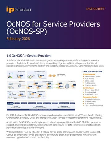
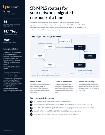
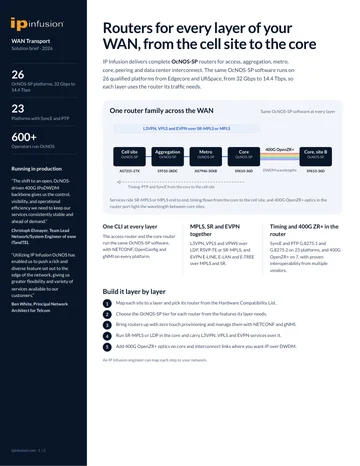
OcNOS-SP 数据手册
表单简短。提交后您的 PDF 将立即在新标签页中打开。
✓ 正在新标签页中打开您的 PDF……
如果未能自动打开,请使用下方链接。
使用 OcNOS 升级到 SR-MPLS
表单简短。提交后您的 PDF 将立即在新标签页中打开。
✓ 正在新标签页中打开您的 PDF……
如果未能自动打开,请使用下方链接。
云与服务提供商 WAN 传输
表单简短。提交后您的 PDF 将立即在新标签页中打开。
✓ 正在新标签页中打开您的 PDF……
如果未能自动打开,请使用下方链接。